Calculate The Rotational Inertia Of A Wheel
News Leon
Mar 31, 2025 · 6 min read
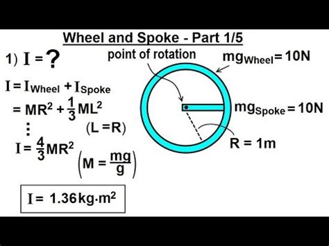
Table of Contents
Calculating the Rotational Inertia of a Wheel: A Comprehensive Guide
Understanding rotational inertia, also known as the moment of inertia, is crucial in various fields of physics and engineering, particularly when dealing with rotating objects like wheels. This comprehensive guide will delve into the intricacies of calculating the rotational inertia of a wheel, exploring different methods, scenarios, and the underlying principles involved. We'll cover everything from simple uniform wheels to more complex scenarios, equipping you with the knowledge to tackle diverse problems.
What is Rotational Inertia?
Before diving into calculations, let's solidify our understanding of rotational inertia. It's a measure of an object's resistance to changes in its rotational motion. Think of it as the rotational equivalent of mass in linear motion. A larger rotational inertia means a greater resistance to angular acceleration or deceleration. This resistance depends not only on the mass of the object but also on how that mass is distributed relative to the axis of rotation. Mass farther from the axis contributes more significantly to the rotational inertia.
Factors Affecting Rotational Inertia
Several factors influence a wheel's rotational inertia:
-
Mass (m): A greater mass inherently leads to a higher rotational inertia. More mass means more resistance to changes in rotation.
-
Mass Distribution (r): The distribution of mass relative to the axis of rotation is paramount. Mass concentrated further from the axis significantly increases rotational inertia compared to the same mass concentrated closer to the axis. This is why a hollow cylinder has a higher rotational inertia than a solid cylinder of the same mass.
-
Shape: The shape of the wheel plays a crucial role. A solid disc, a thin hoop, and a spoked wheel all have different rotational inertia even if they possess the same mass.
-
Axis of Rotation: The location of the axis of rotation influences the rotational inertia. Rotating a wheel about an axis through its center will yield a different result compared to rotating it about an axis at its edge.
Calculating Rotational Inertia: Different Wheel Types
The calculation method varies depending on the wheel's shape and mass distribution. Let's examine some common scenarios:
1. Solid Cylinder or Disc
This is a fundamental case. A solid cylinder or disc has its mass uniformly distributed. The formula for its rotational inertia (I) about an axis through its center and perpendicular to its circular face is:
I = (1/2) * m * r²
where:
- m is the mass of the cylinder or disc
- r is the radius of the cylinder or disc
2. Thin Hoop or Ring
A thin hoop or ring has its mass concentrated at its outer edge. Its rotational inertia about an axis through its center and perpendicular to its plane is:
I = m * r²
Notice that the rotational inertia of a hoop is twice that of a solid disc with the same mass and radius. This highlights the significant impact of mass distribution.
3. Hollow Cylinder
For a hollow cylinder, the rotational inertia is given by:
I = (1/2) * m * (R² + r²)
where:
- m is the mass of the hollow cylinder
- R is the outer radius
- r is the inner radius
4. Spoked Wheel: A More Complex Scenario
A spoked wheel presents a more complex calculation. The spokes contribute significantly to the total inertia. The precise calculation requires considering the mass and distribution of both the rim and the spokes. Often, simplification techniques and approximations are used. One approach might involve modeling the spokes as thin rods and using the appropriate formula for the rotational inertia of a rod, then adding the inertia of the rim (often approximated as a thin hoop). However, this method requires making assumptions about the spoke material, thickness, and precise geometry, which may lead to inaccuracies. More sophisticated computational methods like Finite Element Analysis (FEA) might be necessary for highly accurate results.
Parallel Axis Theorem: Shifting the Axis of Rotation
The parallel axis theorem is invaluable when calculating the rotational inertia about an axis that's parallel to but not identical to an axis passing through the center of mass. The theorem states:
I = I<sub>cm</sub> + m * d²
where:
- I is the rotational inertia about the parallel axis
- I<sub>cm</sub> is the rotational inertia about the axis through the center of mass
- m is the mass of the object
- d is the distance between the two parallel axes
For example, if you want to calculate the rotational inertia of a solid cylinder about an axis along its edge, you would use the rotational inertia formula for a solid cylinder about its central axis (I<sub>cm</sub> = (1/2)mr²) and then apply the parallel axis theorem with d = r (the distance between the two axes).
Practical Applications and Considerations
The concept of rotational inertia has wide-ranging applications:
-
Vehicle Design: Engineers use rotational inertia calculations to optimize the design of vehicle wheels and tires for better handling, acceleration, and braking.
-
Robotics: Rotational inertia is crucial in designing and controlling robotic arms and other rotating mechanisms.
-
Flywheels: Flywheels, used for energy storage, rely heavily on the principle of rotational inertia to store kinetic energy.
-
Gyroscopes: Understanding rotational inertia is fundamental to the operation of gyroscopes, which maintain their orientation in space.
It's important to remember that the calculations presented above assume idealized scenarios. In real-world situations, factors such as material non-uniformity, imperfections in shape, and the presence of additional components (like bearings and hubs) can affect the actual rotational inertia. These factors often necessitate more complex calculations or experimental determination of the rotational inertia.
Advanced Techniques for Complex Wheel Geometries
For wheels with intricate geometries, analytical calculations become cumbersome or impossible. In such cases, numerical methods become essential. These include:
-
Finite Element Analysis (FEA): FEA divides the object into numerous small elements, and then, using computational power, approximates the total rotational inertia by summing the contributions of each element. It's a powerful tool capable of handling complex geometries and material properties.
-
Experimental Determination: In situations where analytical or numerical methods are impractical, experimental determination of rotational inertia is possible. This involves using techniques like the physical pendulum method or a torsion pendulum to measure the wheel's rotational properties.
Conclusion: Mastering Rotational Inertia Calculations
Calculating the rotational inertia of a wheel is a fundamental concept with far-reaching implications. This guide provided a comprehensive overview of the methods involved, from simple uniform wheels to more complex scenarios. Mastering these calculations is crucial for various engineering and physics applications. Remember to consider the specific shape, mass distribution, and axis of rotation when selecting the appropriate formula. For complex geometries, numerical methods or experimental techniques offer valuable alternative approaches. Through a thorough understanding of these principles, you can confidently analyze and predict the rotational behavior of diverse wheel designs and systems.
Latest Posts
Latest Posts
-
Every Integer Is A Real Number
Apr 01, 2025
-
Count Vowels In A String Python
Apr 01, 2025
-
Which Of The Following Elements Is Most Electronegative
Apr 01, 2025
-
For Which Value Of X Is Abcd A Kite
Apr 01, 2025
-
64 To The Power Of 1 2
Apr 01, 2025
Related Post
Thank you for visiting our website which covers about Calculate The Rotational Inertia Of A Wheel . We hope the information provided has been useful to you. Feel free to contact us if you have any questions or need further assistance. See you next time and don't miss to bookmark.
