Three Different Resistors Are Connected In Series To A Battery.
News Leon
Mar 20, 2025 · 6 min read
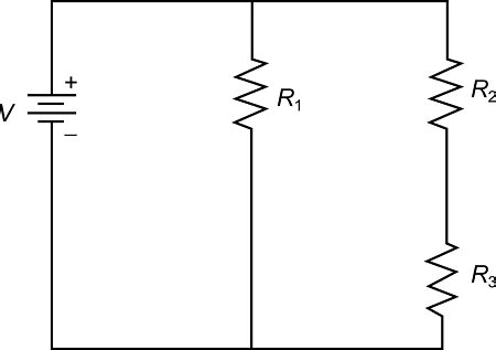
Table of Contents
Three Resistors in Series: A Deep Dive into Circuit Analysis
Connecting resistors in series is a fundamental concept in electrical engineering and electronics. Understanding how resistors behave in series circuits is crucial for designing, troubleshooting, and analyzing a wide range of electronic devices. This article delves into the specifics of a circuit with three resistors connected in series to a battery, exploring the underlying principles, calculations, and practical applications. We'll cover everything from basic concepts to more advanced considerations, ensuring a comprehensive understanding for both beginners and experienced learners.
Understanding Series Circuits
In a series circuit, the components are connected end-to-end, forming a single path for the current to flow. This contrasts with parallel circuits, where components offer multiple paths for current flow. Key characteristics of a series circuit include:
- Single Path for Current: The current flowing through each component in a series circuit is the same. This is a crucial defining characteristic.
- Voltage Division: The total voltage supplied by the battery is divided among the components in the circuit. The voltage across each component is proportional to its resistance.
- Equivalent Resistance: The total resistance of a series circuit is the sum of the individual resistances.
Analyzing the Three-Resistor Series Circuit
Let's consider a circuit with three resistors, R1, R2, and R3, connected in series to a battery with voltage V. The schematic diagram would visually represent these components connected linearly. The current (I) flows from the positive terminal of the battery, through each resistor sequentially, and back to the negative terminal.
Calculating the Equivalent Resistance (Req)
The most significant advantage of connecting resistors in series lies in the simplicity of calculating the total resistance. In a series circuit, the equivalent resistance is simply the sum of the individual resistances:
Req = R1 + R2 + R3
This formula holds true regardless of the number of resistors in the series connection. For our three-resistor example, if R1 = 10 Ω, R2 = 20 Ω, and R3 = 30 Ω, the equivalent resistance would be:
Req = 10 Ω + 20 Ω + 30 Ω = 60 Ω
This means the circuit behaves as if it only contains a single 60 Ω resistor.
Calculating the Current (I)
Once the equivalent resistance is determined, calculating the current flowing through the circuit becomes straightforward using Ohm's Law:
V = I * Req
Rearranging the formula to solve for current:
I = V / Req
If the battery voltage (V) is 12V, then the current in our example circuit would be:
I = 12V / 60 Ω = 0.2 A
This current remains consistent throughout the entire circuit; 0.2A flows through R1, R2, and R3.
Calculating the Voltage Across Each Resistor
The voltage across each resistor can be calculated using Ohm's Law again, but this time applied to each resistor individually:
- V1 = I * R1
- V2 = I * R2
- V3 = I * R3
Using our example values:
- V1 = 0.2 A * 10 Ω = 2V
- V2 = 0.2 A * 20 Ω = 4V
- V3 = 0.2 A * 30 Ω = 6V
Notice that the sum of the individual voltages (V1 + V2 + V3 = 12V) equals the total voltage supplied by the battery. This demonstrates the principle of voltage division in series circuits.
Voltage Divider Rule
The voltage division rule is a convenient shortcut for calculating the voltage across individual resistors in a series circuit. It states that the voltage across a resistor is proportional to its resistance relative to the total resistance. The formula is:
Vr = (R / Req) * V
Where:
- Vr is the voltage across resistor R
- R is the resistance of the individual resistor
- Req is the equivalent resistance of the series circuit
- V is the total voltage applied to the circuit
Using this rule for our example:
- V1 = (10 Ω / 60 Ω) * 12V = 2V
- V2 = (20 Ω / 60 Ω) * 12V = 4V
- V3 = (30 Ω / 60 Ω) * 12V = 6V
This confirms our previous calculations and highlights the usefulness of the voltage divider rule.
Practical Applications of Series Resistors
Series resistor connections have numerous practical applications in electronics and electrical engineering. Some key examples include:
- Current Limiting: Resistors are frequently used in series to limit the current flowing through a component. This is particularly important for protecting sensitive components from excessive current, which could lead to damage or failure.
- Voltage Division: As discussed earlier, series resistors can create a voltage divider, providing different voltage levels from a single power source. This technique is widely used in various circuits for signal processing, amplification, and power regulation.
- Biasing Transistors: In transistor circuits, series resistors are often used to establish the appropriate bias point for optimal operation. This ensures the transistor operates within its intended range and avoids distortion or other performance issues.
- Pull-up and Pull-down Resistors: In digital logic circuits, series resistors are employed as pull-up or pull-down resistors to define the default state of input pins. This prevents floating inputs, which can lead to unpredictable behavior.
- LED Current Limiting: When using LEDs, a series resistor is essential to limit the current to prevent burning out the LED. LEDs have a specific forward voltage and current rating that must be adhered to.
Advanced Considerations: Tolerance and Power Dissipation
While the calculations above provide an idealized view of series resistor circuits, several practical considerations must be factored in for real-world applications.
Resistor Tolerance
Resistors are manufactured with a certain tolerance, meaning their actual resistance may slightly deviate from their nominal value. Common tolerances include ±1%, ±5%, and ±10%. This tolerance needs to be accounted for in circuit design, especially in applications where precise voltage or current levels are critical. The cumulative effect of tolerances on multiple resistors in series can lead to larger deviations from expected values.
Power Dissipation
Each resistor in a series circuit dissipates power according to the formula:
P = I² * R
or
P = V² / R
where:
- P is the power dissipated in watts
- I is the current in amperes
- R is the resistance in ohms
- V is the voltage across the resistor in volts
It's crucial to select resistors with sufficient power rating to handle the power they will dissipate without overheating. Overheating can damage the resistor and potentially other components in the circuit.
Troubleshooting Series Circuits
Troubleshooting series circuits often involves identifying the cause of an open circuit or a short circuit.
- Open Circuit: If a resistor fails (becomes open), the circuit will be broken, and no current will flow. This is easily detected by measuring zero current or voltage across the battery.
- Short Circuit: A short circuit occurs when there's an unintended low-resistance path across a part of the circuit. This can cause excessive current to flow, potentially damaging components or blowing fuses. Detecting short circuits usually involves observing unusually high current readings or burnt components.
Systematic checking of each resistor using a multimeter is an effective approach to troubleshooting.
Conclusion
Understanding series resistor circuits is fundamental to electronics and electrical engineering. The ability to accurately calculate equivalent resistance, current, and voltage across individual resistors is essential for designing and troubleshooting various electronic systems. Remembering the key principles – single current path, voltage division, and the simple summation of resistances for equivalent resistance – will provide a solid foundation for more advanced circuit analysis. Always account for resistor tolerance and power dissipation in practical applications to ensure the circuit's reliability and safety. Finally, familiarizing yourself with common troubleshooting techniques will help you swiftly identify and resolve issues in series resistor networks.
Latest Posts
Latest Posts
-
C2h6 O2 Co2 H2o
Mar 21, 2025
-
How Many Total Electrons Does Carbon Have
Mar 21, 2025
-
Which Of The Following Is Not A Membranous Organelle
Mar 21, 2025
-
The Space Between The Cornea And The Iris Is The
Mar 21, 2025
-
What Is A Segment Of Dna Called
Mar 21, 2025
Related Post
Thank you for visiting our website which covers about Three Different Resistors Are Connected In Series To A Battery. . We hope the information provided has been useful to you. Feel free to contact us if you have any questions or need further assistance. See you next time and don't miss to bookmark.
