The Figure Below Shows Two Very Long Straight Wires
News Leon
Mar 28, 2025 · 7 min read
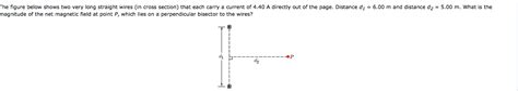
Table of Contents
The Figure Below Shows Two Very Long Straight Wires: Exploring Magnetic Fields and Forces
The image (which is unfortunately not provided, but we will assume it depicts two parallel, infinitely long straight wires carrying currents) presents a classic physics scenario ideal for exploring fundamental concepts in electromagnetism. This article delves into the magnetic fields generated by these wires, the forces they exert on each other, and the applications of these principles. We'll explore various scenarios, including parallel wires with currents flowing in the same and opposite directions, and consider the implications of factors like current magnitude and wire separation.
Understanding the Magnetic Field of a Single Long Straight Wire
Before analyzing the interaction between two wires, let's understand the magnetic field produced by a single, infinitely long, straight wire carrying a current. This field is described by Ampère's Law, a fundamental principle in electromagnetism. Ampère's Law states that the line integral of the magnetic field around a closed loop is proportional to the current enclosed by that loop. For a long straight wire, this simplifies to:
B = (μ₀I) / (2πr)
Where:
- B represents the magnetic field strength (in Tesla).
- μ₀ is the permeability of free space (a constant, approximately 4π x 10⁻⁷ Tm/A).
- I is the current flowing through the wire (in Amperes).
- r is the radial distance from the wire (in meters).
This equation reveals a crucial aspect of the magnetic field: it forms concentric circles around the wire. The field strength is inversely proportional to the distance from the wire; therefore, the field is strongest close to the wire and weakens as you move further away. The direction of the magnetic field can be determined using the right-hand rule: if you grasp the wire with your right hand, your thumb pointing in the direction of the current, your fingers will curl in the direction of the magnetic field.
The Interaction Between Two Parallel Wires: Attraction and Repulsion
Now, let's consider the scenario depicted in the (unseen) figure: two very long, straight wires placed parallel to each other, each carrying a current. Each wire generates its own magnetic field, and this field interacts with the current in the other wire, resulting in a force. This force is described by the Lorentz force law, which states that the force on a current-carrying conductor in a magnetic field is given by:
F = ILBsinθ
Where:
- F is the force (in Newtons).
- I is the current in the wire (in Amperes).
- L is the length of the wire segment (in meters).
- B is the magnetic field strength (in Tesla).
- θ is the angle between the current and the magnetic field.
In our case, the magnetic field acting on one wire is generated by the other wire. Since the wires are parallel, the angle θ between the current and the magnetic field is 90 degrees (sinθ = 1), simplifying the equation to:
F = ILB
Substituting the equation for the magnetic field of a single wire (B = (μ₀I) / (2πr)) into the force equation, we obtain the force per unit length between two parallel wires:
F/L = (μ₀I₁I₂) / (2πd)
Where:
- F/L is the force per unit length (in N/m).
- I₁ and I₂ are the currents in the two wires (in Amperes).
- d is the distance between the two wires (in meters).
This equation illustrates a critical observation:
-
Same Direction Currents: If the currents in both wires flow in the same direction, the force is attractive (F/L is positive). The magnetic fields generated by each wire reinforce each other in the region between the wires, creating a net attractive force.
-
Opposite Direction Currents: If the currents flow in opposite directions, the force is repulsive (F/L is negative). The magnetic fields oppose each other in the region between the wires, creating a net repulsive force.
Applications and Real-World Examples
The principles governing the interaction of parallel current-carrying wires have numerous applications in various fields of science and technology:
1. Electric Motors and Generators:
Electric motors rely on the interaction between magnetic fields and currents to produce rotational motion. The stator (stationary part) contains coils that generate magnetic fields, while the rotor (rotating part) contains current-carrying conductors. The forces between the magnetic fields of the stator and rotor cause the rotor to rotate. Generators operate on a similar principle, converting mechanical energy into electrical energy by utilizing the interaction between moving conductors and magnetic fields.
2. Electromagnets:
Electromagnets utilize the magnetic field generated by a current-carrying coil to create a strong magnetic force. By varying the current, the strength of the magnetic field can be controlled. Electromagnets find applications in numerous devices, including MRI machines, loudspeakers, and lifting magnets. The forces within an electromagnet are essentially a macroscopic manifestation of the forces between many microscopic current loops.
3. Transmission Lines:
High-voltage transmission lines carry large amounts of electrical current over long distances. These lines are often constructed with multiple conductors to reduce the magnetic field and the forces between conductors. Understanding the forces between these wires is crucial to their design and stability. Excessive forces due to high currents can lead to damage and potential failures.
4. Circuit Design:
In the design of printed circuit boards (PCBs), careful consideration is given to the spacing between conductors to minimize inductive effects. The magnetic fields generated by adjacent conductors can lead to unwanted inductance, affecting the performance of the circuit. Understanding the forces between parallel wires is important to reduce this interference and maintain proper circuit functionality.
5. Magnetic Levitation (Maglev) Trains:
Maglev trains utilize the repulsive force between magnets and coils to levitate above the track, eliminating friction and allowing for high speeds. The repulsion between electromagnets on the train and the track is based on the same principle as the repulsion between parallel wires with oppositely directed currents. This sophisticated application demonstrates the power of controlled electromagnetic forces.
Factors Affecting the Force: Current, Distance, and Wire Geometry
Several factors influence the magnitude of the force between two parallel wires:
1. Current Magnitude:
The force is directly proportional to the product of the currents in the two wires (I₁I₂). Increasing either current will proportionally increase the force.
2. Distance Between Wires:
The force is inversely proportional to the distance between the wires (d). As the distance increases, the force decreases rapidly. This is because the magnetic field strength decreases with distance from the wire, as detailed earlier.
3. Wire Geometry:
Our analysis has assumed infinitely long, straight wires. In reality, wires have finite length and may not be perfectly straight. These deviations from the ideal scenario will modify the force calculation. However, for sufficiently long, straight wires, the above equation provides a reasonable approximation.
Beyond Parallel Wires: More Complex Configurations
While the parallel wire scenario provides a foundational understanding of electromagnetic forces, more complex configurations exist. For example, one could investigate the forces between wires that are not parallel, which would involve a more complex vector analysis. Similarly, the analysis could be extended to wires carrying time-varying currents, introducing the complexities of electromagnetic induction. These advanced scenarios provide fertile ground for further investigation and application.
Conclusion
The seemingly simple image of two parallel, current-carrying wires opens a window into the intricate world of electromagnetism. Understanding the magnetic fields produced by each wire and the forces they exert on each other is fundamental to a broad range of applications, from electric motors and generators to advanced technologies like Maglev trains. The equations and principles presented here provide a solid foundation for exploring more complex electromagnetic interactions and advancing our understanding of this fundamental force of nature. The concepts discussed here are vital for engineers, physicists, and anyone interested in the fascinating interplay between electricity and magnetism. Further exploration into these areas will reveal even more profound implications and unlock exciting new technological advancements.
Latest Posts
Latest Posts
-
How To Find Valence Electrons Of Transition Elements
Mar 31, 2025
-
An Account Is Said To Have A Debit Balance If
Mar 31, 2025
-
Select The Equation That Represents The Graph
Mar 31, 2025
-
How Is Temperature Related To The Motions Of Molecules
Mar 31, 2025
-
Which Of The Following Is Expressed Correctly
Mar 31, 2025
Related Post
Thank you for visiting our website which covers about The Figure Below Shows Two Very Long Straight Wires . We hope the information provided has been useful to you. Feel free to contact us if you have any questions or need further assistance. See you next time and don't miss to bookmark.
