The Current In An Rl Circuit Drops From
News Leon
Mar 25, 2025 · 6 min read
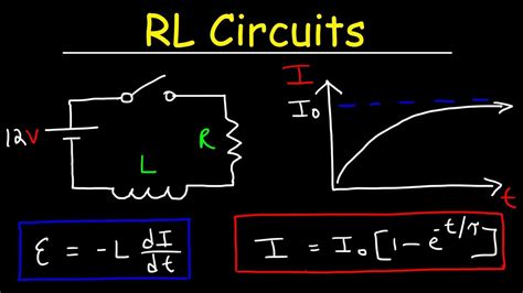
Table of Contents
The Current in an RL Circuit Drops: A Deep Dive into Inductor Behavior
The behavior of current in an RL circuit, specifically how it drops over time, is a fundamental concept in electrical engineering. Understanding this transient response is crucial for designing and analyzing various electronic systems, from simple filters to complex power supplies. This article delves into the intricacies of current decay in an RL circuit, exploring the underlying physics, mathematical modeling, and practical implications.
Understanding the RL Circuit
An RL circuit, also known as an RL network, is a circuit comprising a resistor (R) and an inductor (L) connected in series or parallel. The inductor, a passive component, stores energy in a magnetic field when current flows through it. This energy storage is the key to understanding the transient behavior of the circuit. Unlike a resistor, which dissipates energy as heat, an inductor resists changes in current. This resistance to change is quantified by the inductor's inductance, measured in Henries (H).
The Role of Inductance
Inductance is a measure of an inductor's ability to oppose changes in current. When the current through an inductor increases, it generates a magnetic field, and this field creates a back electromotive force (back EMF) that opposes the change in current. Similarly, when the current decreases, the collapsing magnetic field induces a back EMF that tries to maintain the current flow. This self-induced EMF is governed by Faraday's law of induction.
The Time Constant: τ = L/R
The key parameter governing the rate of current change in an RL circuit is the time constant, denoted by τ (tau). It's defined as the ratio of the inductance (L) to the resistance (R): τ = L/R. The time constant represents the time it takes for the current to reach approximately 63.2% of its final value during charging or to drop to approximately 36.8% of its initial value during discharging.
Current Decay in an RL Circuit: The Mathematical Model
When the source voltage is removed from a series RL circuit, the current doesn't instantly drop to zero. Instead, it decays exponentially over time. This decay is described by the following equation:
i(t) = I₀ * e^(-t/τ)
Where:
- i(t) is the current at time t.
- I₀ is the initial current (at t = 0).
- e is the base of the natural logarithm (approximately 2.718).
- t is the time elapsed since the voltage source was removed.
- τ is the time constant (L/R).
This equation reveals that the current decays exponentially, approaching zero asymptotically. It never truly reaches zero in a finite time, but it becomes negligible after a few time constants.
Analyzing the Equation: Understanding the Decay
Let's break down the equation to understand its implications:
-
Exponential Decay: The presence of the exponential term, e^(-t/τ), indicates the characteristic exponential decay of the current. The negative sign ensures that the current decreases with time.
-
Time Constant's Influence: The time constant, τ, plays a crucial role. A larger time constant (larger L or smaller R) leads to a slower decay, meaning the current takes longer to drop significantly. Conversely, a smaller time constant results in faster decay.
-
Initial Current: I₀ represents the initial current flowing through the circuit just before the voltage source is removed. This value is critical in determining the initial conditions for the decay process.
Practical Implications and Applications
Understanding current decay in RL circuits has significant implications in various applications:
1. Switch-Mode Power Supplies (SMPS):
SMPS utilize inductors to store and release energy efficiently. The decay of current in the inductor during the switching cycle is crucial for smooth operation and minimizing energy loss. Precise control over the current decay ensures efficient power conversion.
2. Inductive Load Switching:
Switching inductive loads, like motors or solenoids, without proper consideration of the current decay can lead to voltage spikes and damage to components. The back EMF generated during the current decay can be quite significant and requires careful management, often using snubber circuits or freewheeling diodes.
3. RL Filters:
RL circuits are used in filters to attenuate specific frequency ranges. The transient response, including the current decay, influences the filter's performance, particularly its ability to handle transient signals. Understanding the current decay helps in designing filters with desired characteristics.
4. Relay Circuits:
Relays often incorporate inductors in their coils. The current decay in the coil determines how quickly the relay releases its contacts. Understanding this decay is crucial for timing applications and avoiding contact bouncing issues.
5. Pulse Width Modulation (PWM):
PWM techniques, widely used in motor control and power electronics, rely on the controlled switching of inductive loads. Precise control over the inductor current's decay is vital for achieving the desired modulation of the output power.
Beyond the Simple Series RL Circuit
The analysis presented so far focuses on a simple series RL circuit. However, the principles can be extended to more complex circuits:
Parallel RL Circuits:
In a parallel RL circuit, the current from the source splits between the resistor and the inductor. The decay of the inductor current follows a similar exponential pattern, but the overall circuit behavior is different due to the parallel configuration.
RL Circuits with Multiple Inductors and Resistors:
Analyzing circuits with multiple inductors and resistors requires applying more advanced techniques, such as mesh analysis or nodal analysis. However, the fundamental principles of exponential decay remain the same for each individual inductor.
Experimental Verification and Simulation
The exponential decay of current in an RL circuit can be experimentally verified using an oscilloscope. By observing the voltage across the resistor, which is directly proportional to the current, one can confirm the exponential decay predicted by the mathematical model. Moreover, circuit simulation software like LTSpice or Multisim can be utilized to model the circuit and verify the theoretical predictions.
Troubleshooting and Common Issues
Several issues might arise when dealing with RL circuits:
-
Incorrect Component Values: Using incorrect resistor or inductor values can significantly alter the time constant and the current decay profile. Precise measurement and selection of components are essential.
-
Parasitic Capacitance: All components possess some level of parasitic capacitance, which can affect the transient response. In high-frequency applications, the impact of parasitic capacitance can be noticeable.
-
Saturated Inductors: If the inductor core saturates, its inductance changes, and the current decay pattern deviates from the ideal exponential decay.
-
Component Tolerances: The tolerances of resistors and inductors can cause variations in the time constant and the observed current decay.
Conclusion
The current in an RL circuit doesn't drop instantly when the source voltage is removed. Instead, it decays exponentially over time, governed by the circuit's time constant (τ = L/R). Understanding this exponential decay is paramount for designing and analyzing numerous electrical systems. This article provides a comprehensive understanding of the underlying physics, mathematical modeling, practical applications, and potential issues associated with the current decay in RL circuits. By grasping these concepts, engineers can effectively design and troubleshoot circuits that incorporate inductive elements and ensure their reliable operation. The principles discussed here form the foundation for understanding more complex circuits and control systems.
Latest Posts
Latest Posts
-
What Are Characteristics Of A Base
Mar 29, 2025
-
What Phase Is The Reverse Of Prophase
Mar 29, 2025
-
Mechanical Advantage Of A 1st Class Lever
Mar 29, 2025
-
What Is Half A Byte Called
Mar 29, 2025
-
Multicellular Heterotrophs Without A Cell Wall
Mar 29, 2025
Related Post
Thank you for visiting our website which covers about The Current In An Rl Circuit Drops From . We hope the information provided has been useful to you. Feel free to contact us if you have any questions or need further assistance. See you next time and don't miss to bookmark.
