In The Figure The Magnetic Flux Through The Loop
News Leon
Mar 29, 2025 · 5 min read
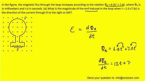
Table of Contents
In the Figure: Understanding Magnetic Flux Through a Loop
Magnetic flux, a fundamental concept in electromagnetism, quantifies the amount of magnetic field passing through a given area. Understanding magnetic flux is crucial for grasping numerous phenomena, from electromagnetic induction to the operation of electric generators and transformers. This article delves deep into the intricacies of magnetic flux, specifically focusing on how it's calculated and interpreted when dealing with a loop in a magnetic field. We will explore various scenarios, including loops with varying orientations and non-uniform magnetic fields.
What is Magnetic Flux?
Magnetic flux (Φ) is a scalar quantity representing the total magnetic field that passes through a given area. It's a measure of the "amount" of magnetism. Imagine a surface; magnetic flux is the number of magnetic field lines penetrating that surface. The more field lines, the higher the flux. Mathematically, it's defined as:
Φ = B ⋅ A = BA cos θ
Where:
- Φ represents the magnetic flux (measured in Webers, Wb).
- B is the magnetic field strength (measured in Teslas, T).
- A is the area of the surface (measured in square meters, m²).
- θ is the angle between the magnetic field vector (B) and the area vector (A). The area vector is a vector perpendicular to the surface; its direction is conventionally defined using the right-hand rule.
Understanding the Area Vector
The area vector (A) is a crucial element in understanding magnetic flux. It's a vector whose magnitude is equal to the area and whose direction is perpendicular to the surface. The direction is determined using the right-hand rule: if you curl the fingers of your right hand in the direction of the boundary of the surface, your thumb points in the direction of the area vector. This seemingly simple detail is essential for correctly calculating the flux, particularly when dealing with loops in complex orientations.
The Significance of the Cosine Term
The cosine term (cos θ) accounts for the orientation of the loop relative to the magnetic field.
- θ = 0° (B parallel to A): cos θ = 1; maximum flux. The magnetic field lines are perpendicular to the loop and pass directly through it.
- θ = 90° (B perpendicular to A): cos θ = 0; zero flux. The magnetic field lines are parallel to the loop and do not penetrate it.
- 0° < θ < 90°: The flux is a fraction of the maximum possible flux.
Calculating Magnetic Flux Through a Loop: Different Scenarios
Let's explore different scenarios of loops in magnetic fields to better grasp the calculation of magnetic flux.
1. Uniform Magnetic Field, Loop Perpendicular to the Field
This is the simplest scenario. If the magnetic field (B) is uniform and the loop is perpendicular to the field, then θ = 0°, and cos θ = 1. The formula simplifies to:
Φ = BA
This means the flux is simply the product of the magnetic field strength and the area of the loop.
2. Uniform Magnetic Field, Loop at an Angle to the Field
When the loop is at an angle (θ) to the magnetic field, we must use the full formula:
Φ = BA cos θ
Here, θ is the angle between the magnetic field vector and the area vector of the loop. Accurate determination of θ is critical for precise calculation.
3. Non-Uniform Magnetic Field
In a non-uniform magnetic field, the magnetic field strength (B) varies across the area of the loop. In such cases, calculating the total flux becomes more complex. We can't simply use the formula Φ = BA cos θ. Instead, we need to break the loop into infinitesimally small areas (dA) and integrate the flux over the entire area:
Φ = ∫ B ⋅ dA
This integral represents the summation of the flux through each small area element. The solution to this integral depends on the specific nature of the non-uniform field.
4. Loops with Multiple Turns
Many applications involve coils or solenoids, which are essentially loops with multiple turns. The total flux through an N-turn coil is simply N times the flux through a single turn:
Φ<sub>total</sub> = NΦ
where N is the number of turns.
Applications of Magnetic Flux Calculations
Understanding magnetic flux is crucial in many areas of physics and engineering:
-
Electromagnetic Induction: Faraday's Law of Induction states that a changing magnetic flux through a loop induces an electromotive force (EMF) in the loop. This principle underpins the operation of generators, transformers, and many other electrical devices.
-
Electric Motors: Electric motors utilize the interaction between magnetic fields and current-carrying loops to produce rotational motion. The magnetic flux plays a central role in determining the torque generated by the motor.
-
Magnetic Resonance Imaging (MRI): MRI uses strong magnetic fields and radio waves to create detailed images of the inside of the body. Understanding the magnetic flux through the body is crucial for interpreting the resulting images.
-
Magnetic Sensors: Various magnetic sensors are based on the principle of detecting changes in magnetic flux. These sensors have wide applications in various fields such as automotive, aerospace, and industrial automation.
Advanced Concepts and Considerations
While the basic principles of magnetic flux are relatively straightforward, several advanced considerations can increase the complexity of calculations:
-
Time-Varying Magnetic Fields: If the magnetic field changes over time, the induced EMF is proportional to the rate of change of magnetic flux (dΦ/dt), as stated by Faraday's Law.
-
Mutual Inductance: When two coils are placed close together, a changing current in one coil can induce a voltage in the other coil due to the changing magnetic flux linking both coils. This phenomenon is known as mutual inductance.
Conclusion
Understanding magnetic flux is fundamental to comprehending various electromagnetic phenomena. Calculating the magnetic flux through a loop requires careful consideration of the magnetic field strength, the area of the loop, and the angle between the magnetic field and the loop's area vector. While straightforward in simple scenarios, the calculation can become more complex in cases of non-uniform magnetic fields or time-varying fields. The ability to correctly calculate and interpret magnetic flux is essential for engineers and physicists working with electromagnetic systems. This article has provided a comprehensive overview of the subject, equipping you with the knowledge to tackle a wide range of problems involving magnetic flux through loops. Remember, thorough understanding of the vector nature of magnetic field and area vectors, coupled with a grasp of integral calculus for non-uniform fields, are keys to mastering this crucial concept.
Latest Posts
Latest Posts
-
Which Factors Would Increase The Rate Of A Chemical Reaction
Apr 01, 2025
-
How Many Days Are In 2016
Apr 01, 2025
-
Naoh Is Strong Or Weak Base
Apr 01, 2025
-
What Is The Decimal For 11 12
Apr 01, 2025
-
Carbon Dioxide Is Held Together By This Type Of Bond
Apr 01, 2025
Related Post
Thank you for visiting our website which covers about In The Figure The Magnetic Flux Through The Loop . We hope the information provided has been useful to you. Feel free to contact us if you have any questions or need further assistance. See you next time and don't miss to bookmark.
