In The Figure A Rectangular Loop Of Wire With Length
News Leon
Mar 20, 2025 · 6 min read
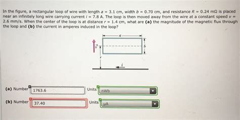
Table of Contents
Analyzing a Rectangular Loop of Wire: Magnetic Flux, Induced EMF, and Applications
The humble rectangular loop of wire, seemingly simple in its geometry, serves as a foundational element in understanding a vast array of electromagnetic phenomena. From electric generators to transformers and inductors, its behavior under varying magnetic fields dictates the functionality of countless electrical devices. This article delves into the physics governing a rectangular loop of wire within a magnetic field, exploring concepts of magnetic flux, induced electromotive force (EMF), and practical applications.
Understanding Magnetic Flux
Before we analyze the loop itself, we need to grasp the concept of magnetic flux (Φ). Magnetic flux is a measure of the total magnetic field that passes through a given area. It's calculated as the product of the magnetic field strength (B), the area (A) of the loop, and the cosine of the angle (θ) between the magnetic field lines and the normal to the loop's surface:
Φ = B A cos θ
The units of magnetic flux are webers (Wb). Crucially, the flux is maximized when the magnetic field is perpendicular to the loop (θ = 0°), and zero when the field is parallel to the plane of the loop (θ = 90°).
Faraday's Law of Induction and Induced EMF
The cornerstone of understanding the behavior of a rectangular loop in a changing magnetic field is Faraday's Law of Induction. This law states that a changing magnetic flux through a loop of wire induces an electromotive force (EMF) – essentially, a voltage – in the loop. Mathematically:
EMF = -dΦ/dt
The negative sign signifies Lenz's Law, which dictates that the induced current will flow in a direction that opposes the change in magnetic flux. In simpler terms, the loop tries to resist the change in the magnetic field that caused the EMF.
Analyzing a Rectangular Loop in a Uniform Magnetic Field
Let's consider a rectangular loop of wire with length 'l' and width 'w' placed in a uniform magnetic field, B. If the loop is stationary and the magnetic field is constant, the magnetic flux through the loop is constant, and therefore, no EMF is induced (dΦ/dt = 0).
However, things get interesting when we introduce motion. Consider the following scenarios:
1. The Loop Moves Perpendicular to the Magnetic Field:
If the loop moves with a velocity 'v' perpendicular to both its plane and the magnetic field, the area of the loop intersecting the magnetic field changes with time. This change in magnetic flux induces an EMF. The magnitude of the induced EMF depends on the velocity, magnetic field strength, length of the loop, and the angle between the velocity and the magnetic field.
2. The Loop Rotates in the Magnetic Field:
If the loop rotates within the magnetic field, the angle θ between the magnetic field and the normal to the loop changes. This variation in θ leads to a time-varying magnetic flux, and thus, an induced EMF. This principle is fundamental to the operation of electric generators. The induced EMF will be sinusoidal in nature, reaching its maximum value when the plane of the loop is perpendicular to the magnetic field and zero when it is parallel.
3. The Magnetic Field Strength Changes:
Even if the loop remains stationary, a change in the magnetic field strength (B) over time will result in a changing magnetic flux and, consequently, an induced EMF. This principle is the foundation of transformers. A changing magnetic field produced by one coil (primary) induces a voltage in a second coil (secondary) placed nearby.
Calculating Induced EMF: Detailed Examples
Let's delve into more specific calculations.
Example 1: Loop Moving Perpendicularly
Imagine a rectangular loop with length l = 0.5m and width w = 0.3m moving with a velocity v = 2 m/s perpendicular to a uniform magnetic field B = 0.8 T. The magnetic flux is given by Φ = BAw. As the loop moves, the area A changes over time. Assuming the loop moves such that the area intersecting the field decreases, we can calculate the rate of change of area, dA/dt, as -wv (negative because the area is decreasing). Therefore, the induced EMF is:
EMF = -dΦ/dt = -B(dA/dt) = -B(-wv) = Bwv = 0.8 T * 0.3 m * 2 m/s = 0.48 V
Example 2: Rotating Loop
Consider the same loop rotating with an angular velocity ω in the same magnetic field. The angle θ between the normal to the loop and the magnetic field is given by θ = ωt. The magnetic flux is Φ = BAcos(ωt) = B(lw)cos(ωt). The induced EMF is:
EMF = -dΦ/dt = B(lw)ωsin(ωt)
This equation shows the sinusoidal nature of the induced EMF in a rotating loop. The maximum EMF occurs when sin(ωt) = 1.
Practical Applications of Rectangular Loops
The principles discussed above underpin a wide range of crucial technologies:
-
Electric Generators: Generators utilize rotating rectangular loops (or coils of wire) within a magnetic field to generate electricity. The rotational motion creates a changing magnetic flux, inducing an EMF that drives current through an external circuit.
-
Transformers: Transformers employ changing magnetic fields to transfer electrical energy between coils of wire. A changing current in the primary coil creates a changing magnetic flux, inducing a voltage in the secondary coil. The voltage in the secondary coil can be stepped up or stepped down depending on the ratio of turns in the primary and secondary coils.
-
Inductors: Inductors, often consisting of a coiled wire, oppose changes in current. When current flows through an inductor, it creates a magnetic field. A change in current causes a change in this magnetic field, inducing an EMF that opposes the original current change. This self-induced EMF is described by the concept of self-inductance.
-
Electric Motors: While not directly using a single rectangular loop, electric motors employ the interaction of magnetic fields and current-carrying loops (often multiple coils arranged in a specific configuration) to produce rotational motion. The principles of induced EMF and magnetic forces are at play.
-
Wireless Charging: Inductive charging systems use changing magnetic fields generated by a transmitting coil to induce a current in a receiving coil, effectively transferring electrical energy wirelessly.
Advanced Concepts and Considerations
The analysis presented so far assumes ideal conditions. In reality, factors like:
-
Resistance of the Wire: The resistance of the wire in the loop leads to energy losses in the form of heat (Joule heating). This reduces the efficiency of energy conversion in devices like generators and motors.
-
Self-Inductance: The current flowing in the loop itself generates a magnetic field, which can affect the induced EMF. This self-induced EMF opposes changes in current and is characterized by the self-inductance of the loop.
-
Mutual Inductance: When two or more loops are close together, their magnetic fields interact. This interaction is characterized by mutual inductance, influencing the induced EMF in each loop.
-
Non-Uniform Magnetic Fields: In many real-world applications, the magnetic field is not uniform. This complicates the calculation of magnetic flux and induced EMF. Numerical methods or advanced mathematical techniques are often required for accurate analysis.
Conclusion
The rectangular loop of wire, although simple in appearance, is a powerful tool for understanding fundamental principles of electromagnetism. Its behavior under varying magnetic fields forms the foundation for numerous technological applications, ranging from electric power generation to wireless charging. A thorough grasp of magnetic flux, Faraday's Law, and related concepts is vital for anyone seeking to design, analyze, or comprehend the functionality of a broad range of electrical and electromechanical devices. Further exploration into advanced concepts and the use of computational techniques can reveal deeper insights into the intricacies of electromagnetic phenomena involving rectangular loops and more complex coil configurations.
Latest Posts
Latest Posts
-
In A Nuclear Experiment A Proton With Kinetic Energy
Mar 20, 2025
-
Whats The Mass Of A Proton
Mar 20, 2025
-
What Is The Difference Between A Milligram And A Milliliter
Mar 20, 2025
-
What Does The Slope Of A Distance Time Graph Indicate
Mar 20, 2025
-
Why Do Bones Heal Faster Than Cartilage
Mar 20, 2025
Related Post
Thank you for visiting our website which covers about In The Figure A Rectangular Loop Of Wire With Length . We hope the information provided has been useful to you. Feel free to contact us if you have any questions or need further assistance. See you next time and don't miss to bookmark.
