In The Figure A Metal Rod Is Forced To Move
News Leon
Mar 27, 2025 · 6 min read
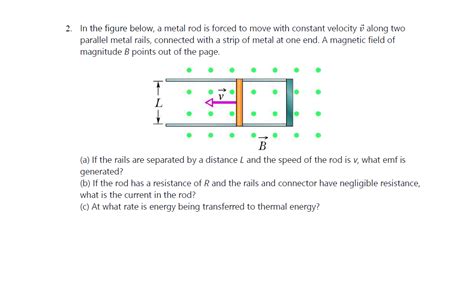
Table of Contents
In the Figure: A Metal Rod Forced to Move – Exploring Electromagnetic Induction
The seemingly simple scenario – a metal rod forced to move within a magnetic field – unlocks a fascinating world of physics, specifically electromagnetic induction. This principle, discovered by Michael Faraday, is the cornerstone of countless technologies we use daily, from electric generators to wireless charging. Let's delve deep into this phenomenon, exploring the underlying principles, mathematical descriptions, and practical applications.
Understanding Electromagnetic Induction
At the heart of this lies Faraday's Law of Induction. This law states that a changing magnetic field induces an electromotive force (EMF), or voltage, in a conductor. This "changing" aspect is crucial; a stationary rod in a constant magnetic field will experience no induced EMF. The movement of the rod, therefore, introduces the necessary change in the magnetic flux linking the rod.
Magnetic Flux: The Key Player
Magnetic flux (Φ) represents the total magnetic field passing through a given area. Its value depends on the strength of the magnetic field (B), the area (A) through which the field passes, and the angle (θ) between the field lines and the area vector:
Φ = B * A * cos(θ)
When the rod moves, the area enclosed by the rod and the magnetic field changes, thus altering the magnetic flux. This change in flux is what induces the EMF.
Lenz's Law: Opposing the Change
Lenz's Law provides a crucial addition to Faraday's Law. It dictates that the direction of the induced EMF opposes the change in magnetic flux that produced it. This opposition is a consequence of the conservation of energy; the induced current creates its own magnetic field that tries to counteract the original change.
Mathematical Description: Calculating the Induced EMF
The quantitative relationship between the induced EMF (ε) and the rate of change of magnetic flux is given by Faraday's Law:
ε = -dΦ/dt
The negative sign signifies Lenz's Law. For a rod of length 'l' moving with velocity 'v' perpendicular to a uniform magnetic field 'B', the induced EMF can be expressed as:
ε = B * l * v
This equation highlights the direct proportionality between the induced EMF and the magnetic field strength, the length of the rod, and its velocity.
The Role of Resistance and Current
The induced EMF drives a current through the rod, provided there's a closed circuit. The magnitude of this current (I) is determined by Ohm's Law:
I = ε / R
where R is the resistance of the rod and the circuit. The current's direction is governed by Lenz's Law, ensuring it opposes the change in magnetic flux.
Practical Applications: From Generators to Sensors
The principle of electromagnetic induction underpins many essential technologies:
1. Electric Generators: Powering the World
Electric generators are perhaps the most significant application. They employ rotating coils of wire within a magnetic field. The rotation continuously changes the magnetic flux linking the coils, inducing an alternating EMF which then powers our homes and industries. The larger the generator, the higher the power output; this is directly related to the stronger magnetic field and the faster rotation.
2. Induction Motors: Driving Industrial Machinery
Induction motors utilize the interaction between a rotating magnetic field and induced currents in a rotor to generate torque. The rotating magnetic field induces currents in the rotor windings, creating a magnetic field that interacts with the stator's magnetic field, resulting in rotation. These motors are ubiquitous in industrial applications due to their robustness and reliability.
3. Metal Detectors: Finding Hidden Objects
Metal detectors use the principle of electromagnetic induction to detect metallic objects. They generate a fluctuating magnetic field, and any nearby metal object alters this field, inducing a current that the detector senses. The strength and frequency of this induced current indicate the size and type of metal. Different frequencies are used for different types of metals. This is particularly effective for finding buried metal objects because the changing magnetic field can penetrate the ground.
4. Wireless Charging: Convenient Power Transfer
Wireless charging pads employ electromagnetic induction to transfer power without physical contact. The charging pad generates a magnetic field, which induces a current in the receiving coil within the device. The efficiency of this process depends on factors such as distance between coils, coil alignment, and frequency.
5. Magnetic Flow Meters: Measuring Fluid Flow
In industrial settings, magnetic flow meters leverage electromagnetic induction to measure the flow rate of conductive liquids. Electrodes placed across the pipe detect the voltage induced by the movement of the liquid through a magnetic field. The induced voltage is directly proportional to the flow rate. This technology is crucial for accurate fluid monitoring in various industries.
6. Tachometers: Measuring Rotational Speed
Tachometers measure the rotational speed of machinery. Some tachometers use electromagnetic induction; a magnetic pickup senses the changes in a magnetic field caused by rotating components, such as gear teeth. This induces a voltage whose frequency is proportional to the rotational speed. This non-contact approach offers a reliable measurement without requiring physical connection to the rotating shaft.
Factors Affecting the Induced EMF
Several factors influence the magnitude of the induced EMF:
-
Strength of the magnetic field (B): A stronger magnetic field leads to a higher induced EMF. Powerful electromagnets are often used in applications requiring a significant EMF.
-
Length of the conductor (l): A longer conductor moving within the magnetic field experiences a larger induced EMF.
-
Velocity of the conductor (v): A faster-moving conductor results in a higher rate of change of magnetic flux, hence a larger induced EMF.
-
Angle between the magnetic field and the conductor: The induced EMF is maximized when the conductor moves perpendicular to the magnetic field (θ = 90°).
-
Resistance of the circuit (R): While resistance doesn't directly affect the induced EMF, it influences the resulting current. Higher resistance leads to lower current.
Advanced Concepts and Applications
The basic principle of electromagnetic induction discussed above forms the foundation for more complex scenarios. These include:
-
Moving coils in non-uniform magnetic fields: The induced EMF becomes more complex to calculate, often requiring integration techniques.
-
Rotating conductors: The change in magnetic flux is more intricate, involving trigonometric functions.
-
Self-induction and inductance: A changing current in a coil itself induces an EMF (self-inductance), a concept crucial in inductors and transformers.
-
Mutual induction: The changing current in one coil induces an EMF in a nearby coil (mutual inductance), the basis for transformers and inductive coupling.
Conclusion
The seemingly simple scenario of a metal rod forced to move within a magnetic field reveals the powerful principle of electromagnetic induction. This phenomenon is far from theoretical; it underpins countless technologies essential to modern life. Understanding Faraday's Law and Lenz's Law provides a fundamental understanding of how electricity and magnetism intertwine, leading to advancements across various fields, from power generation and industrial automation to sophisticated sensors and wireless technology. Further exploration into the advanced aspects of this principle unlocks even more possibilities for innovation and technological progress. Continued research and development in this area promise even more exciting applications in the future.
Latest Posts
Latest Posts
-
What Is In Car Battery Acid
Mar 31, 2025
-
The Only Movable Joint In The Skull Is Between The
Mar 31, 2025
-
Which Inequality Is Shown In The Graph Below
Mar 31, 2025
-
Which Mrna Sequence Complements The Dna Sequence Below
Mar 31, 2025
-
Square Root Of 6 Is Irrational
Mar 31, 2025
Related Post
Thank you for visiting our website which covers about In The Figure A Metal Rod Is Forced To Move . We hope the information provided has been useful to you. Feel free to contact us if you have any questions or need further assistance. See you next time and don't miss to bookmark.
