The Figure Displays Two Circuits With A Charged Capacitor
News Leon
Mar 14, 2025 · 7 min read
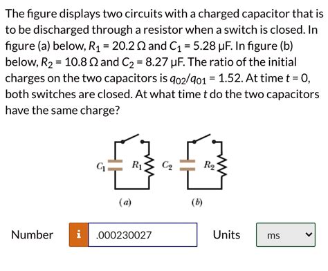
Table of Contents
The Figure Displays Two Circuits with a Charged Capacitor: A Deep Dive into RC Circuits and Transient Analysis
The ubiquitous capacitor, a fundamental component in electronics, stores energy in an electric field. When a capacitor is charged and then connected to a resistor, it creates a fascinating dynamic system known as an RC circuit. This article delves into the behavior of such circuits, specifically analyzing two common scenarios illustrated by the hypothetical "figure" mentioned in the prompt. We'll explore the transient response, time constants, and applications of these crucial circuits. We will also cover crucial aspects of circuit analysis related to voltage, current, and energy transfer.
Understanding RC Circuits: A Foundation
Before diving into the specifics of the hypothetical figure, let's establish a solid understanding of RC circuits. An RC circuit is a simple electrical circuit consisting of a resistor (R) and a capacitor (C) connected in series or parallel. The behavior of these circuits is governed by the interplay between the resistor, which dissipates energy as heat, and the capacitor, which stores and releases energy.
The key characteristic of an RC circuit is its time constant (τ), defined as the product of the resistance and capacitance: τ = RC. This time constant represents the time it takes for the voltage across the capacitor to reach approximately 63.2% of its final value during charging, or to decay to approximately 36.8% of its initial value during discharging. Understanding the time constant is crucial for predicting the circuit's behavior.
Charging a Capacitor
When a charged capacitor is connected to a resistor, the capacitor begins to discharge. The voltage across the capacitor (Vc) decreases exponentially with time, following this equation:
Vc(t) = V₀ * e^(-t/RC)
Where:
- Vc(t) is the voltage across the capacitor at time t
- V₀ is the initial voltage across the capacitor
- t is the time elapsed
- R is the resistance
- C is the capacitance
- e is the base of the natural logarithm (approximately 2.718)
This equation highlights the exponential decay nature of the discharging process. The time constant, RC, dictates the rate of decay. A larger time constant signifies a slower discharge. After one time constant (t = RC), the voltage across the capacitor has dropped to approximately 37% of its initial value.
Discharging a Capacitor
Conversely, when an uncharged capacitor is connected to a voltage source through a resistor, it begins to charge. The voltage across the capacitor (Vc) increases exponentially with time, following this equation:
Vc(t) = V(1 - e^(-t/RC))
Where:
- Vc(t) is the voltage across the capacitor at time t
- V is the source voltage
- t is the time elapsed
- R is the resistance
- C is the capacitance
- e is the base of the natural logarithm (approximately 2.718)
This equation illustrates the exponential growth of the voltage across the capacitor during charging. Again, the time constant, RC, determines the rate of charging. After one time constant (t = RC), the voltage across the capacitor has risen to approximately 63% of the source voltage.
Analyzing the Hypothetical Figure: Two Circuits
Without the specific details of the "figure," we'll explore two common scenarios involving charged capacitors and resistors, covering both series and parallel configurations.
Scenario 1: Series RC Circuit (Charging and Discharging)
Imagine the figure displays a series RC circuit. A charged capacitor is initially connected to a resistor. This circuit will exhibit an exponential discharge, with the voltage across the capacitor decreasing over time as described by the discharging equation above. The current flowing through the resistor will also decrease exponentially.
Key Observations:
- Initial Voltage: The voltage across the capacitor starts at its initial charged value (V₀).
- Exponential Decay: The voltage decreases exponentially towards zero.
- Time Constant: The rate of decay is governed by the time constant, RC.
- Energy Dissipation: The energy stored in the capacitor is dissipated as heat in the resistor.
This simple circuit is fundamental in many applications, such as timing circuits, filters, and simple pulse generators.
Analyzing the Current in the Series Circuit
The current (I) in the series circuit during discharge is given by:
I(t) = (V₀/R) * e^(-t/RC)
Notice that the current also decays exponentially with the same time constant, RC. This means the initial current is highest and then gradually decreases as the capacitor discharges.
Scenario 2: Parallel RC Circuit (Charging and Discharging Considerations)
Now consider a scenario where the "figure" shows a parallel RC circuit. A charged capacitor is connected across a resistor. In this case, the discharging process is different. The capacitor discharges directly through the resistor without any series impedance.
Key Observations:
- Initial Voltage: The voltage across the capacitor and resistor are initially equal to the charged capacitor's voltage (V₀).
- Exponential Decay (identical to series): The voltage across both the capacitor and the resistor decreases exponentially according to the discharging equation.
- Time Constant (identical to series): The rate of decay is still determined by the time constant, RC.
- Current Paths: The discharge current flows directly through the resistor, unlike the series configuration where it flows through both components sequentially.
The parallel RC circuit, while seemingly simpler, also has its practical applications. It's less commonly used for timing applications but can be found in various filtering and decoupling circuits.
Analyzing the Current in the Parallel Circuit
Unlike the series case, the current in the parallel circuit is slightly more complex due to multiple paths. The current flowing through the resistor (Ir) is given by:
Ir(t) = Vc(t) / R = V₀/R * e^(-t/RC)
This equation directly reflects the exponential decay of the capacitor voltage. The total current might involve other circuit elements not mentioned in the simplified model.
Applications of RC Circuits
RC circuits find wide applications across various electronic systems due to their simple yet versatile nature:
-
Timing Circuits: RC circuits are extensively used in timing circuits to generate time delays or control the duration of pulses. Examples include timers in microcontrollers, simple oscillators, and pulse-width modulation (PWM) circuits.
-
Filtering: RC circuits act as simple filters that attenuate certain frequencies while allowing others to pass. Low-pass filters allow low-frequency signals to pass while attenuating high-frequency signals, and high-pass filters do the opposite. These are essential components in audio processing, signal conditioning, and noise reduction.
-
Coupling and Decoupling: RC circuits are frequently used for coupling and decoupling signals in different parts of a circuit. They prevent unwanted DC signals from interfering with AC signals or isolate different parts of a circuit to avoid signal distortion.
-
Wave Shaping: By choosing appropriate resistor and capacitor values, RC circuits can shape waveforms, such as smoothing pulses or creating specific signal profiles.
-
Power Supplies: RC circuits are used in power supplies to filter out noise and ripple in the output voltage. They help stabilize the voltage provided to sensitive electronic components.
Beyond the Basics: Advanced Concepts
While we have focused on basic RC circuit analysis, many advanced concepts extend the understanding of these circuits:
-
Complex Impedances: At higher frequencies, the impedance of the capacitor becomes frequency-dependent, leading to more complex circuit analysis involving complex numbers and phasors.
-
Frequency Response: Analyzing the frequency response of RC circuits involves studying how the circuit behaves across a range of frequencies, leading to the concept of Bode plots and cutoff frequencies.
-
Non-linear Capacitors: In certain applications, capacitors may exhibit non-linear behavior, complicating the analysis and requiring numerical methods for accurate modeling.
-
Spice Simulation: Software packages such as SPICE (Simulation Program with Integrated Circuit Emphasis) are used to simulate the behavior of complex circuits, including RC circuits, providing a valuable tool for design and analysis.
Conclusion
The simple RC circuit, despite its apparent simplicity, is a foundational element in electronics and serves as a building block for more complex systems. Understanding the behavior of charged capacitors in both series and parallel configurations is crucial for designing and analyzing a wide range of electronic circuits. The time constant, RC, is the key parameter governing the transient response and determining the circuit's behavior over time. The exponential nature of charging and discharging is a recurring theme that underscores the unique characteristics of these circuits and their diverse applications in numerous electronic systems. By grasping the fundamentals and exploring the advanced concepts, engineers and enthusiasts alike can harness the power of RC circuits in numerous innovative designs.
Latest Posts
Latest Posts
-
A Helicopter Lifts A 72 Kg Astronaut
Mar 14, 2025
-
What Capacitance Is Required To Store An Energy Of
Mar 14, 2025
-
What Is The Major Product Of The Following Reaction Sequence
Mar 14, 2025
-
How Many Lightyears Is The Sun
Mar 14, 2025
-
Convert Timestamp To Date Time Python
Mar 14, 2025
Related Post
Thank you for visiting our website which covers about The Figure Displays Two Circuits With A Charged Capacitor . We hope the information provided has been useful to you. Feel free to contact us if you have any questions or need further assistance. See you next time and don't miss to bookmark.
