In The Figure Five Long Parallel Wires
News Leon
Mar 29, 2025 · 6 min read
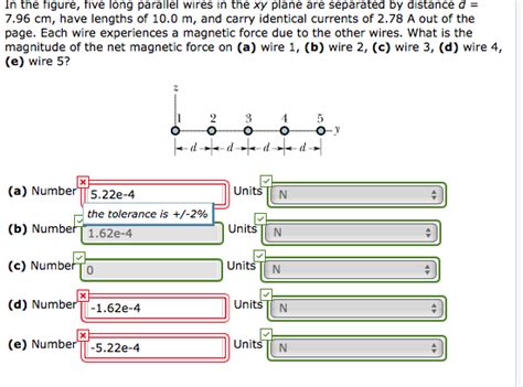
Table of Contents
In the Figure: Five Long Parallel Wires – A Deep Dive into Magnetic Fields and Forces
This article delves into the fascinating world of electromagnetism, specifically analyzing the magnetic fields and forces generated by five long, parallel wires carrying current. We'll explore the underlying principles, derive relevant equations, and examine various scenarios to fully understand the interplay of these currents and their resulting magnetic effects. This comprehensive guide will cover everything from basic concepts to complex calculations, equipping you with a strong foundation in this fundamental area of physics.
Understanding the Basics: Magnetic Fields and the Biot-Savart Law
Before we tackle the complexities of five parallel wires, let's refresh our understanding of fundamental concepts. A current-carrying wire generates a magnetic field around it. This field is described by the Biot-Savart Law:
dB = (μ₀/4π) * (Idl x r) / r³
Where:
- dB: is the infinitesimal contribution to the magnetic field.
- μ₀: is the permeability of free space (a constant).
- I: is the current in the wire.
- dl: is an infinitesimal length vector along the wire.
- r: is the vector from the infinitesimal length element (dl) to the point where the field is being calculated.
- r³: is the cube of the magnitude of the vector r.
- x: represents the cross product.
The cross product in the equation indicates that the magnetic field is perpendicular to both the current direction and the vector pointing from the wire to the point of observation. This leads to the well-known right-hand rule, which helps visualize the direction of the magnetic field lines circling the wire.
The Magnetic Field of a Single Long Straight Wire
For a long, straight wire carrying a current I, the Biot-Savart Law can be integrated to yield a simpler expression for the magnetic field at a distance r from the wire:
B = (μ₀I)/(2πr)
This equation reveals that the magnetic field strength is inversely proportional to the distance from the wire. The field lines are concentric circles around the wire, with the direction given by the right-hand rule (curl your fingers in the direction of the current, and your thumb points in the direction of the magnetic field).
Superposition Principle: Combining Multiple Wires
When dealing with multiple current-carrying wires, the principle of superposition comes into play. This principle states that the total magnetic field at any point is the vector sum of the individual magnetic fields produced by each wire. This means we can calculate the magnetic field produced by each wire separately using the formula above and then add the resulting vectors to find the net magnetic field.
Analyzing Five Parallel Wires: Various Scenarios
Now, let's consider the case of five long, parallel wires. The complexity of the problem depends significantly on the arrangement of the wires and the direction of the currents they carry. Let's explore some common scenarios:
Scenario 1: Five Wires with Currents in the Same Direction
If all five wires carry currents in the same direction (let's say, upwards), the magnetic fields produced by each wire will reinforce each other in the region between the wires. The net magnetic field will be strongest in the center of the arrangement and will decrease as you move away from the center. Calculating the precise magnetic field at any point would involve summing the vector contributions from each wire using the formula mentioned above. This calculation will be significantly more involved than for a single wire.
Scenario 2: Alternating Currents in Parallel Wires
Suppose the currents alternate in direction; for example, upwards, downwards, upwards, downwards, and upwards. This arrangement will lead to a more complex interplay of magnetic fields. The magnetic fields from adjacent wires with opposite currents will partially cancel each other out. The net magnetic field will be a complex function of the distance from each wire and the current magnitudes. Specific calculations would require detailed vector addition considering the direction and magnitude of the magnetic field generated by each wire.
Scenario 3: Unequal Currents in Parallel Wires
In a more realistic scenario, the currents in the wires might not be equal. This adds another layer of complexity to the calculation. The contributions of each wire to the net magnetic field will be weighted by the magnitude of its current. Points closer to wires with larger currents will experience a more substantial magnetic field from that wire, impacting the overall net field. Again, vector addition is crucial to determine the net field.
Scenario 4: Wires Arranged in a Specific Geometry
The arrangement of the wires themselves significantly impacts the resulting magnetic field. If the wires are arranged in a specific geometric pattern, such as a square or a pentagon, the symmetry can simplify the calculation. In such symmetric arrangements, some components of the magnetic fields might cancel out, allowing for easier determination of the net field.
Forces Between Parallel Wires: Ampere's Law
The magnetic fields generated by the parallel wires also interact with each other, resulting in forces between the wires. Ampere's Law provides the framework for calculating these forces. Ampere's Law states that the line integral of the magnetic field around a closed loop is proportional to the current enclosed by that loop. When applied to two parallel wires, it reveals that the force per unit length between two parallel wires carrying currents I₁ and I₂ and separated by a distance r is:
F/L = (μ₀I₁I₂)/(2πr)
This force is attractive if the currents are in the same direction and repulsive if the currents are in opposite directions. For five parallel wires, calculating the total force on any one wire involves summing the pairwise forces between that wire and each of the other four wires. This requires considering both the magnitude and direction of each pairwise force. Again, the geometric arrangement of the wires significantly influences the resultant forces.
Advanced Considerations: Magnetic Moments and Other Effects
For a complete understanding, several advanced considerations are crucial:
- Magnetic Moments: The interaction between the magnetic fields generated by the currents can induce magnetic moments in materials placed in the vicinity of the wires. This can further complicate the magnetic field distribution.
- Skin Effect: At high frequencies, the current distribution within the wires isn't uniform, concentrating near the surface (skin effect). This non-uniform current distribution affects the magnetic field calculation.
- Proximity Effect: The presence of other wires alters the current distribution in each wire (proximity effect). This needs to be considered for precise calculations, particularly in closely spaced wire configurations.
Conclusion
Analyzing the magnetic fields and forces generated by five long, parallel wires is a complex but rewarding undertaking. Understanding the interplay of the Biot-Savart Law, superposition principle, and Ampere's Law is essential. The complexity escalates depending on the direction of currents, their magnitudes, and the geometric arrangement of the wires. While simple scenarios allow for relatively straightforward calculations, more complex situations require sophisticated techniques for accurate results. This comprehensive exploration should provide a robust understanding of the foundational principles and equip you with the necessary tools to tackle various configurations of parallel wires and their magnetic interactions. The principles discussed here are vital not only for understanding fundamental physics but also for various applications in electrical engineering and other related fields.
Latest Posts
Latest Posts
-
What Is The Mass Of A Beta Particle
Apr 01, 2025
-
12 Of 150 Is What Number
Apr 01, 2025
-
Draw The Organic Products Formed In The Following Reaction
Apr 01, 2025
-
All The Elements In The Same Period Have The Same
Apr 01, 2025
-
What Percentage Of An Hour Is 45 Minutes
Apr 01, 2025
Related Post
Thank you for visiting our website which covers about In The Figure Five Long Parallel Wires . We hope the information provided has been useful to you. Feel free to contact us if you have any questions or need further assistance. See you next time and don't miss to bookmark.
