In The Figure A Long Rectangular Conducting Loop Of Width
News Leon
Mar 18, 2025 · 6 min read
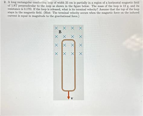
Table of Contents
A Long Rectangular Conducting Loop: Exploring Electromagnetic Induction
The seemingly simple scenario of a long rectangular conducting loop moving through a magnetic field opens a door to a fascinating world of electromagnetic induction. This article delves deep into the physics behind this phenomenon, exploring the concepts of magnetic flux, induced electromotive force (EMF), Lenz's Law, and the implications for various applications. We'll analyze the situation from different perspectives, considering various scenarios like uniform and non-uniform magnetic fields, different loop velocities, and the effects of resistance.
Understanding the Fundamentals: Magnetic Flux and Faraday's Law
Before we delve into the intricacies of the rectangular loop, let's establish a firm grasp on the core principles. The cornerstone of electromagnetic induction is Faraday's Law of Induction, which states that a changing magnetic field induces an electromotive force (EMF) in a closed conducting loop. This EMF, in turn, drives a current. The rate of change of the magnetic field is quantified by the magnetic flux (Φ), which is the measure of the total magnetic field lines passing through a given area. Mathematically, Faraday's Law is expressed as:
ε = -dΦ/dt
where:
- ε represents the induced EMF (in Volts)
- Φ represents the magnetic flux (in Webers)
- t represents time (in seconds)
The negative sign signifies Lenz's Law, which dictates that the induced current's direction opposes the change in magnetic flux that produced it. This is a crucial aspect of understanding the behavior of the loop.
The Rectangular Loop in a Uniform Magnetic Field: A Detailed Analysis
Let's consider a long rectangular conducting loop of width 'w' and length 'l', moving with a constant velocity 'v' through a uniform magnetic field 'B' that is perpendicular to the plane of the loop. Several scenarios arise depending on the orientation of the loop and the direction of its motion:
Scenario 1: Loop Entering the Field
As the loop enters the magnetic field, the area of the loop within the field increases. This increase in area directly translates to an increase in magnetic flux. According to Faraday's Law, this changing flux induces an EMF in the loop. The magnitude of the induced EMF is directly proportional to the rate of change of the magnetic flux:
ε = B * w * v
where:
- B is the magnitude of the magnetic field
- w is the width of the loop
- v is the velocity of the loop
The direction of the induced current can be determined using Lenz's Law. Since the magnetic flux is increasing, the induced current will flow in a direction to oppose this increase – creating its own magnetic field that opposes the external field within the loop.
Scenario 2: Loop Completely Inside the Field
Once the entire loop is inside the uniform magnetic field, the magnetic flux through the loop becomes constant. Consequently, there is no change in magnetic flux (dΦ/dt = 0), resulting in zero induced EMF (ε = 0). No current flows in the loop while it remains completely within the uniform field.
Scenario 3: Loop Leaving the Field
As the loop begins to exit the magnetic field, the area of the loop within the field decreases. This decrease in magnetic flux induces an EMF, but in the opposite direction compared to when the loop entered the field. The magnitude of the induced EMF remains the same:
ε = B * w * v
However, the current's direction, as predicted by Lenz's Law, will now be reversed to oppose the decrease in magnetic flux.
Effects of Resistance and Loop Material
The induced current within the loop depends not only on the induced EMF but also on the resistance of the loop material. Ohm's Law (V = IR) governs the relationship between voltage (EMF), current (I), and resistance (R):
I = ε / R
Therefore, a higher resistance will lead to a smaller induced current, even if the induced EMF remains the same. The material's conductivity plays a significant role; highly conductive materials will allow for larger currents to flow.
The Rectangular Loop in a Non-Uniform Magnetic Field: Added Complexity
Moving to a non-uniform magnetic field significantly complicates the analysis. The magnetic field strength (B) is no longer constant but varies spatially. Consequently, the magnetic flux calculation becomes more intricate, requiring integration over the area of the loop.
The induced EMF is given by:
ε = - d/dt ∫ B.dA
where the integral is taken over the area of the loop. Solving this equation requires a detailed understanding of the magnetic field's spatial variation and how it changes with time as the loop moves. Numerical methods are often employed in such cases.
Practical Applications and Further Considerations
Understanding the behavior of rectangular loops in magnetic fields is crucial for numerous applications. These include:
-
Electric generators: The basic principle of a generator relies on the movement of a coil within a magnetic field, inducing an EMF. Variations in the loop's design, shape, and the magnetic field's strength are used to control the generated voltage and power output.
-
Magnetic sensors: The induced EMF in a moving loop can be used as a means of sensing the presence and strength of a magnetic field. This forms the basis of many magnetic field measurement devices.
-
Eddy current testing: The movement of a conductive loop near a material creates eddy currents within the material. These currents, influenced by material properties and defects, are measured to detect flaws and assess material quality.
Further considerations for a more comprehensive analysis of the rectangular loop involve:
-
Self-inductance: As current flows in the loop, it creates its own magnetic field, which interacts with the external field. This self-inductance affects the transient behavior of the current.
-
Loop's orientation: The angle between the loop's plane and the magnetic field influences the magnetic flux and the induced EMF.
-
Non-constant velocity: If the loop's velocity isn't constant, the induced EMF will vary accordingly, adding further complexity to the calculations.
Conclusion: Bridging Theory and Application
The seemingly simple scenario of a rectangular loop moving in a magnetic field provides a powerful illustration of fundamental electromagnetic principles. Through careful analysis of Faraday's Law, Lenz's Law, and the effects of magnetic field uniformity and loop properties, we can accurately predict the behavior of the system. This understanding forms the bedrock of many technological applications, highlighting the importance of bridging theoretical physics with practical engineering solutions. Further exploration into more complex scenarios, such as non-uniform fields and non-constant velocities, enriches our understanding and opens avenues for more sophisticated applications in the field of electromagnetism. The journey from a simple rectangular loop to complex electromagnetic systems highlights the beauty and power of understanding fundamental principles.
Latest Posts
Latest Posts
-
Which Of The Following Is Not A Form Of Precipitation
Mar 18, 2025
-
Which Statement About Natural Selection Is True
Mar 18, 2025
-
Which Chamber Of Heart Has Thickest Wall
Mar 18, 2025
-
How Many Feet Is 1 2 Miles
Mar 18, 2025
-
How Many Valence Electrons Does Mn Have
Mar 18, 2025
Related Post
Thank you for visiting our website which covers about In The Figure A Long Rectangular Conducting Loop Of Width . We hope the information provided has been useful to you. Feel free to contact us if you have any questions or need further assistance. See you next time and don't miss to bookmark.
