For The Circuit Shown In The Figure
News Leon
Mar 21, 2025 · 6 min read
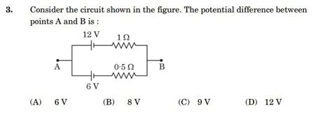
Table of Contents
Analyzing the Circuit: A Comprehensive Guide
This article delves into the analysis of a generic circuit diagram (as no specific figure was provided). We will explore various methods to understand its behavior, including Kirchhoff's laws, nodal analysis, mesh analysis, Thevenin's theorem, and Norton's theorem. The principles discussed are applicable to a wide range of circuits, regardless of their complexity. Understanding these techniques is crucial for electrical engineers, electronics hobbyists, and anyone interested in circuit design and analysis.
Understanding Basic Circuit Components
Before we delve into complex circuit analysis, let's review the fundamental components:
-
Resistors: Resistors impede the flow of current. They are characterized by their resistance (measured in ohms, Ω). Resistors can be connected in series (total resistance is the sum of individual resistances) or parallel (reciprocal of the total resistance is the sum of reciprocals of individual resistances).
-
Capacitors: Capacitors store electrical energy in an electric field. They are characterized by their capacitance (measured in farads, F). Capacitors oppose changes in voltage.
-
Inductors: Inductors store electrical energy in a magnetic field. They are characterized by their inductance (measured in henries, H). Inductors oppose changes in current.
-
Voltage Sources: These provide a constant or time-varying voltage to the circuit. Ideal voltage sources maintain a constant voltage regardless of the current drawn.
-
Current Sources: These provide a constant or time-varying current to the circuit. Ideal current sources maintain a constant current regardless of the voltage across them.
Kirchhoff's Laws: The Foundation of Circuit Analysis
Kirchhoff's Current Law (KCL): The algebraic sum of currents entering a node (a junction point in a circuit) is zero. This implies that the total current entering a node equals the total current leaving the node. This law is based on the principle of charge conservation.
Kirchhoff's Voltage Law (KVL): The algebraic sum of voltages around any closed loop in a circuit is zero. This implies that the voltage drops across components in a loop must equal the voltage rises in that loop. This law is based on the principle of energy conservation.
Applying Kirchhoff's Laws: A Practical Example
Let's consider a simple circuit with two resistors in series connected to a voltage source. Applying KVL, the sum of the voltage drops across each resistor must equal the source voltage. Applying KCL at the node connecting the resistors, the current flowing through each resistor is the same. These simple applications lay the groundwork for more complex circuit analyses.
Nodal Analysis: A Powerful Technique
Nodal analysis is a method that uses KCL to solve for the node voltages in a circuit. It's particularly effective for circuits with multiple voltage sources. The steps involved typically include:
-
Choosing a reference node: This node is assigned a voltage of 0V.
-
Defining node voltages: Assign a voltage variable to each remaining node.
-
Applying KCL: Write a KCL equation for each node, expressing the currents in terms of the node voltages and the component values.
-
Solving the equations: Solve the resulting system of equations to determine the node voltages.
Advantages of Nodal Analysis
- Systematic Approach: Provides a structured approach for solving complex circuits.
- Handles Multiple Sources: Effectively manages circuits with multiple voltage and current sources.
- Efficient for Large Circuits: Can be more efficient than mesh analysis for circuits with many nodes and relatively few loops.
Mesh Analysis: An Alternative Approach
Mesh analysis uses KVL to solve for the loop currents in a circuit. It's particularly efficient for circuits with multiple loops and fewer nodes. The process involves:
-
Defining mesh currents: Assign a current variable to each independent loop in the circuit.
-
Applying KVL: Write a KVL equation for each mesh, expressing the voltage drops across components in terms of the mesh currents and component values.
-
Solving the equations: Solve the resulting system of equations to determine the mesh currents.
Advantages of Mesh Analysis
- Handles Multiple Loops: Effectively manages circuits with multiple loops.
- Intuitive for Loop-Dominated Circuits: Provides an intuitive approach for circuits with many loops and fewer nodes.
Superposition Theorem: Analyzing Circuits with Multiple Sources
The superposition theorem states that in a linear circuit with multiple independent sources, the response (voltage or current) at any point can be determined by summing the individual responses caused by each source acting alone, with all other sources set to zero (voltage sources shorted, current sources open). This is a powerful technique for simplifying the analysis of complex circuits.
Thevenin's Theorem and Norton's Theorem: Simplifying Complex Circuits
Thevenin's Theorem: Any linear circuit can be replaced by an equivalent circuit consisting of a single voltage source (Thevenin voltage, Vth) in series with a single resistor (Thevenin resistance, Rth).
Norton's Theorem: Any linear circuit can be replaced by an equivalent circuit consisting of a single current source (Norton current, In) in parallel with a single resistor (Norton resistance, Rn). Note that Rth = Rn.
These theorems are incredibly useful for simplifying complex circuits, making them easier to analyze and understand. They are particularly helpful when dealing with circuits that have complex load conditions or when analyzing the effect of different loads on a circuit.
Transient Response Analysis: Circuits with Capacitors and Inductors
Circuits containing capacitors and inductors exhibit transient behavior, meaning their response changes over time. Analyzing these circuits involves solving differential equations. Techniques like Laplace transforms are often used to simplify the analysis. The response will typically involve an exponential decay or a damped sinusoidal oscillation depending on the circuit components and their values. The time constants of RC and RL circuits play a crucial role in determining the speed of the transient response.
AC Circuit Analysis: Dealing with Sinusoidal Signals
When dealing with sinusoidal signals (like those found in power systems and communication systems), the analysis techniques change slightly. Concepts like impedance (the AC equivalent of resistance), phasors, and complex numbers are used. Techniques like impedance analysis and phasor diagrams are crucial for understanding the behavior of AC circuits.
Advanced Techniques: Spice Simulation and Numerical Methods
For very complex circuits, software simulations like SPICE (Simulation Program with Integrated Circuit Emphasis) are invaluable. These programs allow for the accurate and efficient analysis of large and intricate circuits. Numerical methods, such as finite element analysis, are also employed for tackling highly complex circuit problems.
Conclusion: A Multifaceted Approach to Circuit Analysis
Analyzing circuits is a multifaceted process that requires a strong understanding of fundamental principles and a variety of analytical techniques. By mastering these methods – Kirchhoff's laws, nodal and mesh analysis, superposition, Thevenin's and Norton's theorems, transient and AC analysis – you can effectively analyze and design a wide range of circuits, from simple resistor networks to intricate integrated circuits. Remember that the choice of method depends on the specific circuit and the information sought. Using software simulations can aid in verification and analysis of more complex scenarios, thus enhancing design confidence and ensuring optimal performance. Continuous learning and exploration of advanced techniques remain key to becoming proficient in circuit analysis.
Latest Posts
Latest Posts
-
What Did Margie Do With A Sigh
Mar 28, 2025
-
What Type Of Bond Is Mgo
Mar 28, 2025
-
Oxidation Number Of Cr In K2cr2o7
Mar 28, 2025
-
Matter Is Anything That Has And Takes Up
Mar 28, 2025
-
Actinoid Contraction Is Greater Than Lanthanoid Contraction
Mar 28, 2025
Related Post
Thank you for visiting our website which covers about For The Circuit Shown In The Figure . We hope the information provided has been useful to you. Feel free to contact us if you have any questions or need further assistance. See you next time and don't miss to bookmark.
