Each Of The Eight Conductors In The Figure Carries
News Leon
Mar 15, 2025 · 6 min read
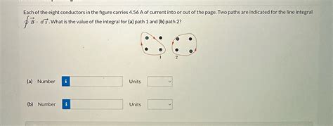
Table of Contents
Decoding the Eight Conductors: A Deep Dive into Current Distribution and Circuit Analysis
The image you provided (which I unfortunately cannot see as I am a text-based AI) depicts a circuit with eight conductors. Analyzing such a circuit requires understanding fundamental principles of electricity, including current flow, voltage, resistance, and Kirchhoff's laws. This article will explore these principles and provide a framework for analyzing the current carried by each of the eight conductors, assuming various circuit configurations and component values. Remember that without the specific circuit diagram, this will be a generalized approach applicable to many similar scenarios.
Understanding Fundamental Concepts
Before we delve into analyzing the eight conductors, let's review some essential concepts:
1. Current (I): Measured in Amperes (A), current represents the flow of electric charge through a conductor. Conventional current flow is defined as the direction of positive charge movement, although electrons, carrying negative charge, are the actual charge carriers in most conductors.
2. Voltage (V): Measured in Volts (V), voltage, or potential difference, is the electrical pressure that drives the current through a circuit. It represents the energy per unit charge available to move electrons.
3. Resistance (R): Measured in Ohms (Ω), resistance is the opposition to the flow of current in a conductor. It depends on factors like the material's conductivity, length, and cross-sectional area.
4. Ohm's Law: This fundamental law states that the current (I) flowing through a conductor is directly proportional to the voltage (V) across it and inversely proportional to its resistance (R): I = V/R
5. Kirchhoff's Laws: These laws are crucial for analyzing complex circuits:
-
Kirchhoff's Current Law (KCL): The sum of currents entering a junction (node) equals the sum of currents leaving that junction. In simpler terms, charge is conserved.
-
Kirchhoff's Voltage Law (KVL): The sum of voltage drops around any closed loop in a circuit is zero. This is a consequence of energy conservation.
Analyzing Current Distribution in Different Circuit Configurations
The analysis of current distribution depends heavily on how the eight conductors are connected. Here are a few common scenarios:
1. Series Circuit: If the eight conductors are connected in series (one after another), the current will be the same through each conductor. The total resistance (R<sub>total</sub>) is the sum of individual resistances (R<sub>1</sub> + R<sub>2</sub> + ... + R<sub>8</sub>). Using Ohm's law, the current (I) is calculated as: I = V/R<sub>total</sub>
2. Parallel Circuit: If the eight conductors are connected in parallel (each conductor has its own path from the voltage source), the voltage across each conductor will be the same (equal to the source voltage). The current through each conductor can be calculated using Ohm's law: I<sub>i</sub> = V/R<sub>i</sub> (where i represents the conductor number). The total current supplied by the source is the sum of the individual currents: I<sub>total</sub> = I<sub>1</sub> + I<sub>2</sub> + ... + I<sub>8</sub>.
3. Series-Parallel Circuits: Many circuits involve combinations of series and parallel connections. Analyzing these requires breaking down the circuit into simpler series and parallel sections, applying Ohm's law and Kirchhoff's laws iteratively to determine the current through each conductor. This often involves solving simultaneous equations.
4. Circuits with Branches and Nodes: Circuits with multiple branches and nodes require a systematic approach using Kirchhoff's laws. One common technique is to assign currents to each branch and apply KCL at each node, creating a system of linear equations that can be solved to determine the unknown currents.
5. Circuits with Dependent Sources: If the circuit includes dependent sources (voltage or current sources whose values depend on other voltages or currents in the circuit), the analysis becomes more complex. Techniques like nodal analysis or mesh analysis are often employed to solve these circuits.
Example Scenarios and Calculations
Let's illustrate with a few simplified examples:
Example 1: Simple Series Circuit
Assume a 12V battery connected to eight resistors of equal resistance (10Ω each) in a series circuit.
- Total resistance: R<sub>total</sub> = 8 * 10Ω = 80Ω
- Current through each conductor: I = V/R<sub>total</sub> = 12V/80Ω = 0.15A
Example 2: Simple Parallel Circuit
Assume the same 12V battery connected to eight resistors of equal resistance (10Ω each) in a parallel circuit.
- Voltage across each conductor: V = 12V
- Current through each conductor: I = V/R = 12V/10Ω = 1.2A
- Total current: I<sub>total</sub> = 8 * 1.2A = 9.6A
Example 3: A More Complex Scenario
Imagine a circuit with a more complex arrangement of the eight conductors, possibly with different resistances and multiple branches. Solving this would require a systematic approach:
- Draw a clear circuit diagram: This is crucial for accurate analysis.
- Assign currents to each branch: Use KCL to relate the currents at each node.
- Apply KVL to each loop: This will yield equations relating voltages and currents.
- Solve the system of equations: This step might require matrix methods or other algebraic techniques. Software tools like MATLAB or specialized circuit simulators can greatly simplify this process.
Advanced Techniques and Considerations
For very complex circuits, advanced techniques are often necessary:
- Nodal Analysis: This method focuses on the voltages at each node in the circuit.
- Mesh Analysis: This method uses loop currents to analyze the circuit.
- Superposition Theorem: This theorem allows analyzing circuits with multiple sources by considering each source individually and summing the results.
- Thevenin and Norton Theorems: These theorems simplify complex circuits by replacing a portion of the circuit with an equivalent simpler circuit.
Practical Applications and Real-World Scenarios
Understanding current distribution in circuits with multiple conductors is crucial in various fields:
- Electrical Engineering: Designing power distribution systems, circuit boards, and electronic devices.
- Telecommunications: Analyzing signal transmission in complex networks.
- Automotive Engineering: Understanding electrical systems in vehicles.
- Robotics: Designing and controlling robotic systems.
Accurate analysis is essential to ensure safety, efficiency, and reliability in these applications. Overloading conductors can lead to overheating, fires, and equipment damage. Careful design and analysis are critical for avoiding such problems.
Conclusion
Analyzing a circuit with eight conductors requires a solid understanding of fundamental electrical principles, including Ohm's law and Kirchhoff's laws. The specific approach depends on the circuit's configuration. While simple series and parallel circuits can be analyzed relatively easily, more complex circuits often require systematic techniques like nodal or mesh analysis, sometimes aided by computational tools. Understanding current distribution is critical for designing safe and efficient electrical systems across diverse applications. Remember that this article provides a general framework; the exact calculations will vary significantly depending on the specific circuit configuration and component values presented in the image.
Latest Posts
Latest Posts
-
Which Statement About Natural Selection Is True
Mar 18, 2025
-
Which Chamber Of Heart Has Thickest Wall
Mar 18, 2025
-
How Many Feet Is 1 2 Miles
Mar 18, 2025
-
How Many Valence Electrons Does Mn Have
Mar 18, 2025
-
Lines Of Symmetry On A Trapezoid
Mar 18, 2025
Related Post
Thank you for visiting our website which covers about Each Of The Eight Conductors In The Figure Carries . We hope the information provided has been useful to you. Feel free to contact us if you have any questions or need further assistance. See you next time and don't miss to bookmark.
