Determine The Resistance R When I 1.5 A
News Leon
Mar 26, 2025 · 6 min read
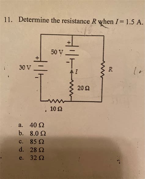
Table of Contents
Determining Resistance (R) When Current (I) is 1.5A: A Comprehensive Guide
Determining the resistance (R) in a circuit when the current (I) is known to be 1.5A requires understanding Ohm's Law and various practical considerations. This guide will comprehensively explore this, covering theoretical foundations, practical applications, and troubleshooting potential issues.
Understanding Ohm's Law: The Foundation of Resistance Calculation
Ohm's Law forms the cornerstone of electrical circuit analysis. It states that the current (I) flowing through a conductor is directly proportional to the voltage (V) applied across it and inversely proportional to its resistance (R). Mathematically, this is represented as:
V = I * R
Where:
- V represents the voltage measured in Volts (V)
- I represents the current measured in Amperes (A)
- R represents the resistance measured in Ohms (Ω)
This simple equation allows us to calculate any of the three variables (V, I, or R) if we know the other two. In our case, we know I (1.5A), so we need to determine V to calculate R.
Rearranging Ohm's Law to Solve for Resistance
To find the resistance (R) when we know the current (I) is 1.5A, we rearrange Ohm's Law:
R = V / I
This equation clearly shows that to determine the resistance, we must know the voltage across the component.
Practical Methods for Determining Voltage and Resistance
Several methods exist to measure the voltage (V) across a component and subsequently calculate the resistance (R). The most common involves using a multimeter.
1. Using a Multimeter: The Standard Approach
A multimeter is an essential tool for any electrical work. It can measure voltage, current, and resistance directly. To determine the resistance when the current is 1.5A:
-
Measure the Voltage (V): Connect the multimeter in parallel with the component where the 1.5A current is flowing. Ensure the multimeter is set to the appropriate voltage range (DC or AC, depending on the circuit). Note down the measured voltage.
-
Calculate the Resistance (R): Substitute the measured voltage (V) and the known current (I = 1.5A) into the rearranged Ohm's Law equation: R = V / 1.5A. The result will be the resistance in Ohms (Ω).
Important Considerations when using a Multimeter:
- Proper Connection: Incorrect connection can damage the multimeter or the circuit. Always double-check the connections before making measurements.
- Appropriate Range: Selecting the correct voltage range on the multimeter is crucial. Choosing a range too low may overload the meter, while a range too high may result in inaccurate readings.
- Circuit State: Ensure the circuit is operating under normal conditions when making measurements. Fluctuations in voltage or current can lead to inaccurate resistance calculations.
2. Using a Known Voltage Source and Current Measurement: An Indirect Approach
If you have a power supply with a known and stable voltage output, you can use this method:
-
Connect the Circuit: Connect the component with unknown resistance to the known voltage source.
-
Measure the Current (I): Use a multimeter set to measure current (Amps) to measure the current flowing through the component. This should ideally be around 1.5A, but minor variations are expected.
-
Calculate the Resistance (R): Use Ohm's Law (R = V / I) to calculate the resistance. Substitute the known voltage (V) from the power supply and the measured current (I) to find the resistance (R).
This method is particularly useful if you're building a circuit and need to verify the resistance of a component before connecting it to a more complex circuit.
3. Using the Color Code on Resistors: A Quick Method for Standard Resistors
Many resistors have color bands that indicate their resistance value. A color code chart can be used to decode this information, providing a quick way to determine the resistance without needing to perform any calculations. However, this method only works for standard, discrete resistors. It does not apply to components with variable or complex resistance characteristics.
Beyond Ohm's Law: Factors Affecting Resistance
While Ohm's Law provides a fundamental understanding, several factors can influence the actual resistance of a component:
1. Temperature: Thermal Effects
The resistance of most materials changes with temperature. For many conductors, resistance increases with increasing temperature (positive temperature coefficient). This effect can be significant, especially at high currents or temperatures. This necessitates temperature compensation in precise applications.
2. Material: Composition Matters
Different materials have different resistivities. The resistivity of a material is an intrinsic property that determines its resistance for a given size and shape. Copper, for instance, has much lower resistivity than Nichrome, leading to significantly different resistance values for the same dimensions.
3. Length and Cross-sectional Area: Geometrical Factors
The resistance of a conductor is directly proportional to its length and inversely proportional to its cross-sectional area. A longer conductor will have higher resistance, while a conductor with a larger cross-sectional area will have lower resistance. This is why thicker wires are used for high-current applications to minimize resistance and heat generation.
4. Frequency: AC Considerations
For alternating current (AC) circuits, the resistance of a component can vary with frequency due to phenomena like skin effect and inductive reactance. At higher frequencies, the current tends to flow near the surface of the conductor (skin effect), increasing effective resistance. Inductance also plays a role in AC circuits, introducing additional impedance beyond the simple resistance.
Troubleshooting and Error Analysis
Inaccurate resistance calculations can stem from various sources:
1. Measurement Errors: Human and Instrumental
Inaccurate readings from the multimeter due to incorrect settings, faulty connections, or poor calibration can lead to errors. Human error in reading and recording values also contributes to inaccuracies.
2. Calibration Issues: Ensuring Accuracy
Regular calibration of the multimeter is essential to maintain accuracy. A miscalibrated multimeter will provide erroneous readings, impacting the resistance calculation.
3. Environmental Factors: External Influences
Temperature fluctuations and other environmental factors can affect resistance measurements. Controlling these variables as much as possible is necessary for precise measurements.
4. Non-Ohmic Behavior: Deviations from Ohm's Law
Some components do not obey Ohm's Law perfectly, exhibiting non-linear resistance characteristics. For these components, the simple equation R = V/I may not provide an accurate representation of their resistance across different voltage or current ranges. Diodes and transistors are classic examples of non-ohmic components.
Advanced Techniques and Applications
For more complex circuits or scenarios, advanced techniques may be necessary:
1. Four-Point Probe Method: Minimizing Lead Resistance
The four-point probe method is used to minimize the effect of lead resistance on resistance measurements, particularly in materials with low resistivity. This method involves using two probes to inject current and two separate probes to measure the voltage drop across the material.
2. Bridge Circuits: Precise Resistance Measurement
Bridge circuits, such as Wheatstone bridges, are used for highly precise resistance measurements. These circuits compare the unknown resistance with known resistances to achieve accurate measurements.
3. Impedance Analysis: AC Circuit Considerations
For AC circuits, impedance analysis is used to consider the combined effect of resistance, capacitance, and inductance. Impedance is a complex quantity that takes into account both the magnitude and phase of the current and voltage.
By understanding Ohm's Law, practical measurement techniques, potential influencing factors, and troubleshooting strategies, one can effectively determine the resistance of a component when the current is 1.5A or any other known value. Remember that accuracy relies heavily on meticulous measurement and consideration of all relevant factors. This comprehensive guide provides a strong foundation for anyone working with electrical circuits and resistance calculations.
Latest Posts
Latest Posts
-
A Slumber Did My Spirit Seal
Mar 29, 2025
-
Letters With A Line Of Symmetry
Mar 29, 2025
-
Marginal Product And Average Product Graph
Mar 29, 2025
-
Which Of The Following Is A Magnetic Storage Device
Mar 29, 2025
-
A Garden Hose With An Internal Diameter
Mar 29, 2025
Related Post
Thank you for visiting our website which covers about Determine The Resistance R When I 1.5 A . We hope the information provided has been useful to you. Feel free to contact us if you have any questions or need further assistance. See you next time and don't miss to bookmark.
