At A Given Instant The Current And Self Induced Emf
News Leon
Mar 23, 2025 · 6 min read
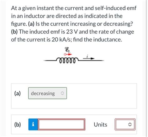
Table of Contents
At a Given Instant: Current and Self-Induced EMF
Understanding the relationship between current and self-induced electromotive force (EMF) is fundamental to comprehending the behavior of inductors and circuits containing inductive elements. This concept is crucial in various applications, from simple electrical circuits to complex power systems and electronic devices. This article delves deep into this relationship, exploring its theoretical foundations and practical implications.
Understanding Self-Induced EMF
Before we examine the instantaneous relationship, let's establish a solid understanding of self-induced EMF. When a current flows through a conductor, it creates a magnetic field around it. This magnetic field is proportional to the current's magnitude. If the current changes, the magnetic field also changes. This changing magnetic field, in turn, induces an electromotive force (EMF) within the conductor itself – a phenomenon known as self-induction.
Lenz's Law: The direction of this self-induced EMF is always such that it opposes the change in current that produced it. This crucial principle, known as Lenz's Law, ensures energy conservation within the system. If the current is increasing, the self-induced EMF acts to reduce the current; if the current is decreasing, the self-induced EMF acts to increase the current.
The Role of Inductance
The magnitude of the self-induced EMF is directly proportional to the rate of change of the current. The constant of proportionality is called inductance (L), measured in Henries (H). Mathematically, this relationship is expressed as:
v = -L(di/dt)
Where:
vrepresents the self-induced EMF (voltage) across the inductor.Lis the inductance of the coil.di/dtrepresents the rate of change of current with respect to time.- The negative sign indicates that the induced EMF opposes the change in current (Lenz's Law).
The inductance (L) itself depends on several factors:
- Number of turns (N): A coil with more turns has higher inductance.
- Coil geometry (length and cross-sectional area): Longer coils with smaller cross-sectional areas have lower inductance.
- Core material: Using a ferromagnetic core significantly increases inductance due to the higher magnetic permeability.
Analyzing Current and Self-Induced EMF at a Given Instant
Let's now focus on the instantaneous relationship. At any given instant in time, the current (i) flowing through the inductor and the self-induced EMF (v) are directly related through the equation mentioned above: v = -L(di/dt). It's crucial to understand that this equation describes the instantaneous values. It's not a simple algebraic equation; it's a differential equation.
Example Scenario: A Simple RL Circuit
Consider a simple RL circuit consisting of a resistor (R) and an inductor (L) connected in series to a DC voltage source (V). When the switch is closed, the current doesn't instantaneously reach its maximum value (V/R) due to the inductor's opposition to the current change. Let's analyze the current and self-induced EMF at different instants:
-
At t=0 (immediately after the switch closes): The current is zero (i=0), but the rate of change of current (di/dt) is at its maximum. Therefore, the self-induced EMF (v) is maximum and equal to the source voltage (V). This is because the inductor initially acts like an open circuit, preventing the immediate flow of current.
-
As time progresses (t>0): The current gradually increases, approaching its steady-state value (V/R). As the current increases, the rate of change of current (di/dt) decreases. Consequently, the self-induced EMF (v) also decreases.
-
At steady state (t→∞): The current reaches its steady-state value (V/R), and the rate of change of current becomes zero (di/dt = 0). Therefore, the self-induced EMF is zero (v=0). The inductor now acts like a short circuit, allowing the current to flow freely.
The current in this RL circuit follows an exponential growth curve, described by the equation:
i(t) = (V/R)(1 - e^(-Rt/L))
By differentiating this equation with respect to time, we can obtain the expression for the instantaneous rate of change of current and subsequently, the instantaneous self-induced EMF.
Practical Implications and Applications
The understanding of the instantaneous relationship between current and self-induced EMF is vital in various applications:
1. Power Supplies and Filters:
Inductors are extensively used in power supplies and filters to smooth out fluctuating DC voltages or to block AC signals. Their ability to oppose rapid current changes is crucial in these applications. The instantaneous self-induced EMF helps to regulate the output voltage and prevent unwanted spikes or ripples.
2. Transformers:
Transformers rely on the principle of mutual inductance, where a changing current in one coil induces a voltage in another. Understanding the instantaneous self-induced EMF in each coil is critical to analyzing the transformer's behavior and its efficiency.
3. Electronic Circuits:
Inductors are used in various electronic circuits, such as oscillators, timers, and resonant circuits. The instantaneous relationship between current and self-induced EMF is essential in designing and analyzing the behavior of these circuits.
4. Electromagnetic Relays:
Electromagnetic relays use electromagnets to switch electrical circuits. The current through the coil and the resulting self-induced EMF play critical roles in the timing and operation of the relay.
5. Spark Ignition Systems:
In spark ignition systems, the self-induced EMF generated by a collapsing magnetic field in an ignition coil is used to generate high-voltage sparks for igniting the fuel-air mixture in internal combustion engines. The rapid change in current creates a very high self-induced EMF.
Advanced Concepts and Considerations
The analysis presented above assumes an ideal inductor with no resistance. However, real-world inductors have some resistance. This resistance affects the current and self-induced EMF, making the analysis more complex. The equations become more intricate, requiring consideration of both the inductive and resistive components.
Furthermore, nonlinear inductors, whose inductance varies with current, present additional challenges. The relationship between current and self-induced EMF is no longer linear, requiring more sophisticated mathematical models for accurate analysis.
Conclusion
The instantaneous relationship between current and self-induced EMF is a cornerstone of electrical engineering. Understanding this fundamental concept, along with Lenz's Law and the role of inductance, provides a solid foundation for analyzing and designing circuits containing inductive components. From simple RL circuits to complex power systems and electronic devices, this relationship governs the behavior of numerous electrical and electronic systems, making it a crucial aspect of electrical engineering knowledge. By understanding the differential equation and its implications, engineers can effectively predict and manipulate the behavior of circuits, leading to efficient and reliable designs. Further exploration into more complex scenarios, involving non-linear elements and AC circuits, will deepen one's comprehension of this essential topic.
Latest Posts
Latest Posts
-
Which Of The Following Is Not A Steroid Hormone
Mar 24, 2025
-
The Layer Of Gases Surrounding Earth Is The
Mar 24, 2025
-
What Is 3 Percent Of 18
Mar 24, 2025
-
In Triangle Abc The Measure Of Angle B Is 90
Mar 24, 2025
-
Write The Iupac Name Of The Compound Shown
Mar 24, 2025
Related Post
Thank you for visiting our website which covers about At A Given Instant The Current And Self Induced Emf . We hope the information provided has been useful to you. Feel free to contact us if you have any questions or need further assistance. See you next time and don't miss to bookmark.
