A Path That An Electric Current Follows Is A
News Leon
Apr 01, 2025 · 7 min read
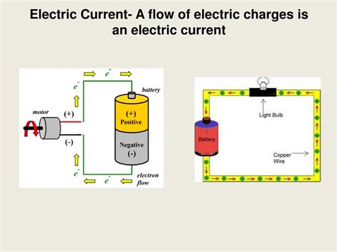
Table of Contents
A Path That an Electric Current Follows Is a: Understanding Circuits and Current Flow
The question, "A path that an electric current follows is a...?" has a simple yet profound answer: a circuit. Understanding circuits is fundamental to comprehending electricity and its applications in our daily lives. This comprehensive guide will delve into the intricacies of circuits, exploring various types, components, and the principles governing current flow. We'll also touch upon the crucial concepts of voltage, resistance, and current, ultimately painting a complete picture of how electricity travels and performs its myriad tasks.
What is a Circuit? The Foundation of Electrical Systems
At its core, an electrical circuit is a closed loop or path through which electric current can flow. Imagine it as a highway system for electrons. Without a complete, unbroken path, electrons cannot flow consistently, and electricity cannot do its work. This closed loop requires several key elements:
Essential Components of a Circuit
-
Power Source: This provides the "push" or electromotive force (EMF) that drives the electrons. Common examples include batteries (direct current or DC) and electrical outlets (alternating current or AC). The power source creates a potential difference, also known as voltage, between two points in the circuit.
-
Conductor: This is the pathway for the current to travel. Typically made of materials with low resistance, like copper or aluminum wires, conductors allow electrons to move freely. The material's ability to conduct electricity is called conductivity.
-
Load: This is the component that consumes the electrical energy and converts it into another form of energy. Examples include light bulbs (converting electrical energy into light and heat), motors (converting electrical energy into mechanical energy), resistors (converting electrical energy into heat), and many more. Loads represent the reason we use circuits – to accomplish specific tasks.
-
Switch (Optional but Common): This is a device used to control the flow of current in the circuit. An open switch breaks the circuit, stopping the flow of current, while a closed switch completes the circuit, allowing current to flow.
Types of Circuits: Exploring the Variety
Circuits aren't all the same. They come in various configurations, each designed for specific purposes. Understanding these differences is crucial for designing and troubleshooting electrical systems.
1. Series Circuits: Simple, but with Limitations
In a series circuit, components are connected end-to-end, forming a single pathway for the current. The current flowing through each component is the same. However, the total resistance is the sum of the individual resistances of each component. This means that adding more components increases the total resistance, leading to a decrease in current flow. A failure of any single component in a series circuit will break the entire circuit, causing a complete interruption of current flow. This is a key limitation of series circuits.
2. Parallel Circuits: Efficiency and Redundancy
A parallel circuit features components connected across each other, providing multiple pathways for the current. The voltage across each component is the same, while the total current is the sum of the currents flowing through each branch. The overall resistance is less than the resistance of the smallest component. Parallel circuits offer greater flexibility and robustness. If one component fails, the rest continue to function, unlike in series circuits. Most household wiring utilizes parallel circuits to ensure that a faulty appliance doesn't disrupt the entire home's electrical system.
3. Combined Circuits: The Real World
Most real-world circuits are a combination of series and parallel configurations. These combined circuits offer the advantages of both types while providing increased complexity and functionality. Analyzing these circuits often requires understanding both series and parallel circuit principles to determine voltage, current, and resistance in various parts of the circuit.
Voltage, Current, and Resistance: The Ohm's Law Trio
The behavior of electricity within a circuit is governed by three fundamental quantities: voltage, current, and resistance. These are inextricably linked through Ohm's Law, a cornerstone of electrical engineering.
Voltage (V): The Electrical Pressure
Voltage, measured in volts (V), represents the electrical potential difference between two points in a circuit. It's the "electrical pressure" that drives the electrons through the circuit. A higher voltage means a greater "push" on the electrons, resulting in a larger current flow.
Current (I): The Flow of Electrons
Current, measured in amperes (A) or amps, represents the rate of flow of electric charge. It's essentially the number of electrons passing a given point in a circuit per unit of time. A larger current signifies a greater flow of electrons.
Resistance (R): Opposition to Current Flow
Resistance, measured in ohms (Ω), represents the opposition to the flow of current in a circuit. Different materials possess different levels of resistance. Conductors have low resistance, allowing current to flow easily, while insulators have high resistance, significantly impeding current flow. Resistors are electronic components specifically designed to introduce a controlled amount of resistance into a circuit.
Ohm's Law: The Connecting Principle
Ohm's Law elegantly connects voltage, current, and resistance: V = I * R
This equation states that the voltage across a conductor is directly proportional to the current flowing through it and the resistance of the conductor. By knowing any two of these quantities, one can calculate the third. This law is essential for circuit analysis and design.
AC vs. DC: The Two Main Types of Current
Electrical current comes in two primary forms: alternating current (AC) and direct current (DC).
Direct Current (DC): One-Way Flow
In DC circuits, the current flows in one direction only. Batteries are a prime example of DC power sources. The voltage and current remain relatively constant over time. DC circuits are simpler to analyze and are commonly used in portable electronics, battery-powered devices, and certain industrial applications.
Alternating Current (AC): The Oscillating Wave
In AC circuits, the current periodically reverses its direction. Household outlets provide AC power, typically at a frequency of 50 or 60 Hertz (Hz), meaning the current changes direction 50 or 60 times per second. AC power is more efficient for long-distance transmission than DC, hence its prevalence in power grids.
Circuit Protection: Safeguarding Against Overloads
Protecting circuits from overloads and short circuits is critical for safety and the longevity of electrical equipment. Several methods are employed:
Fuses: The Sacrificial Defenders
Fuses are designed to melt and break the circuit if the current exceeds a predetermined value. They effectively sacrifice themselves to prevent damage to other components or even fires.
Circuit Breakers: The Resettable Guardians
Circuit breakers function similarly to fuses but are resettable. When an overload occurs, they trip, interrupting the current. Once the cause of the overload is addressed, they can be reset, restoring power. Circuit breakers offer greater convenience than fuses, eliminating the need for replacement after each overload.
Advanced Concepts and Applications
The principles discussed so far form the foundation for understanding more complex aspects of electric circuits and their applications.
Kirchhoff's Laws: Analyzing Complex Networks
Kirchhoff's Laws provide a more advanced framework for analyzing complex circuits containing multiple loops and branches. Kirchhoff's Current Law (KCL) states that the sum of currents entering a node (junction) equals the sum of currents leaving the node. Kirchhoff's Voltage Law (KVL) states that the sum of voltages around any closed loop in a circuit is zero. These laws are indispensable for solving circuit problems involving multiple sources and components.
Capacitors and Inductors: Energy Storage Elements
Capacitors and inductors are crucial components in many electronic circuits. Capacitors store electrical energy in an electric field, while inductors store energy in a magnetic field. They play vital roles in filtering, timing circuits, and energy storage systems.
Conclusion: The Path to Understanding Electricity
The path that an electric current follows is a circuit – a fundamental concept underlying the operation of countless electrical and electronic devices. Understanding circuits involves comprehending the interplay between voltage, current, resistance, and the different circuit configurations. This knowledge is essential for anyone working with electricity, from basic household wiring to advanced electronics design and beyond. By grasping these fundamental principles, you can navigate the world of electricity with confidence and safety.
Latest Posts
Latest Posts
-
What Is Equivalent Fraction Of 4 5
Apr 02, 2025
-
Organelle Where Cellular Respiration Takes Place
Apr 02, 2025
-
What Number Is 45 Of 60
Apr 02, 2025
-
Is Oxygen A Solid Liquid Or A Gas
Apr 02, 2025
-
Which Of The Following Is A Source Of Income
Apr 02, 2025
Related Post
Thank you for visiting our website which covers about A Path That An Electric Current Follows Is A . We hope the information provided has been useful to you. Feel free to contact us if you have any questions or need further assistance. See you next time and don't miss to bookmark.
