Two Long Straight Wires Are Separated By 0.120 M
News Leon
Mar 26, 2025 · 7 min read
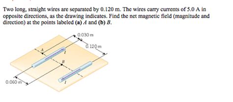
Table of Contents
Two Long Straight Wires Separated by 0.120 m: A Deep Dive into Magnetic Fields and Forces
The seemingly simple scenario of two long, straight wires separated by a distance of 0.120 meters presents a rich opportunity to explore fundamental concepts in electromagnetism. This seemingly simple setup allows us to delve into the intricacies of magnetic fields generated by current-carrying conductors, the forces these fields exert on each other, and the applications of these principles in various technological domains. This article will provide a comprehensive analysis of this system, covering everything from basic principles to more advanced considerations.
Understanding the Magnetic Field of a Single Wire
Before analyzing the interaction between two wires, let's first establish a clear understanding of the magnetic field produced by a single, infinitely long, straight wire carrying a current. This is a cornerstone concept in electromagnetism, described by Ampère's Law.
Ampère's Law and its Application
Ampère's Law states that the line integral of the magnetic field B around a closed loop is equal to the permeability of free space (μ₀) times the current (I) enclosed by the loop. Mathematically, this is represented as:
∮ B ⋅ dl = μ₀I
For an infinitely long, straight wire, the magnetic field lines form concentric circles around the wire. Using Ampère's Law and symmetry arguments, we can derive the magnitude of the magnetic field at a distance 'r' from the wire:
B = (μ₀I) / (2πr)
This equation reveals a crucial relationship: the magnetic field strength is inversely proportional to the distance from the wire. The closer you are to the wire, the stronger the magnetic field. The direction of the magnetic field is determined by the right-hand rule: if you point your thumb in the direction of the current, your fingers curl in the direction of the magnetic field.
The Interaction Between Two Parallel Wires: Magnetic Force
Now, let's consider the scenario of two long, straight, parallel wires separated by a distance of 0.120 m. Each wire carries a current, and these currents will generate magnetic fields that interact with each other, resulting in a force between the wires.
The Force on a Current-Carrying Wire in a Magnetic Field
A current-carrying wire placed in an external magnetic field experiences a force. The magnitude of this force is given by:
F = ILB sinθ
where:
- F is the force
- I is the current in the wire
- L is the length of the wire in the magnetic field
- B is the magnetic field strength
- θ is the angle between the wire and the magnetic field
Calculating the Force Between Two Parallel Wires
To determine the force between our two parallel wires, we need to consider that each wire generates its own magnetic field and experiences the magnetic field produced by the other wire. Let's assume both wires carry the same current, I. The magnetic field produced by one wire at the location of the other wire is given by the equation derived from Ampère's Law:
B = (μ₀I) / (2πd)
where 'd' is the separation distance between the wires (0.120 m in this case). Substituting this into the force equation, we find the force per unit length on one wire due to the other:
F/L = (μ₀I²) / (2πd)
This equation shows that the force per unit length between two parallel wires is directly proportional to the square of the current and inversely proportional to the distance between them. The direction of the force can be determined using the right-hand rule: if the currents are flowing in the same direction, the wires attract each other; if the currents are flowing in opposite directions, the wires repel each other.
Exploring Different Current Scenarios
Let's analyze several scenarios with varying current values to illustrate the impact on the force between the wires.
Scenario 1: Equal and Opposite Currents
If both wires carry currents of, say, 10 Amperes, but in opposite directions, the force between them will be repulsive. Using the equation above, we can calculate the force per unit length. The value of μ₀ (permeability of free space) is approximately 4π x 10⁻⁷ T·m/A.
F/L = (4π x 10⁻⁷ T·m/A * (10 A)²) / (2π * 0.120 m) ≈ 1.67 x 10⁻⁴ N/m
This means that for every meter of wire length, there's a repulsive force of approximately 1.67 x 10⁻⁴ Newtons.
Scenario 2: Equal and Parallel Currents
If both wires carry currents of 10 Amperes in the same direction, the force will be attractive. The magnitude of the force per unit length remains the same, but the direction is attractive. This attractive force can be used to advantage in various applications.
Scenario 3: Unequal Currents
If the currents are unequal, the calculation becomes slightly more complex. The magnetic field produced by each wire will be different, and the force on each wire will need to be calculated separately, taking into account the field produced by the other wire. However, the fundamental principles remain the same, governed by Ampere's Law and the force equation for a current-carrying wire in a magnetic field.
Applications and Real-World Implications
The principles governing the interaction of parallel wires carrying currents find extensive applications in various fields:
-
Electric Motors and Generators: The force between current-carrying conductors forms the basis of operation for electric motors and generators. The interaction of magnetic fields and currents creates torque, enabling the conversion of electrical energy into mechanical energy (motors) or vice-versa (generators).
-
Electromagnets: Electromagnets use the magnetic field generated by current-carrying coils of wire to create strong magnetic fields. This has numerous applications, including lifting heavy objects, magnetic resonance imaging (MRI), and particle accelerators.
-
Transmission Lines: In high-voltage power transmission lines, the forces between parallel wires carrying large currents need to be considered in the design and construction of these lines. These forces can be significant and need to be accounted for to ensure structural stability and safety.
-
Circuit Boards: Although at a smaller scale, the forces between current-carrying traces on circuit boards also exist. While often negligible, they can become significant in high-current circuits or densely packed boards.
-
Magnetic Levitation (Maglev) Trains: Maglev trains utilize the repulsive force between magnets and coils to levitate the train above the track, eliminating friction and allowing for high speeds. This principle leverages the same underlying principles discussed here, albeit on a much larger scale.
Advanced Considerations
This discussion has focused primarily on idealized conditions – infinitely long, straight wires. In reality, wires have finite length, and their geometry can significantly influence the magnetic field distribution and the forces between them.
-
Finite Wire Length: For wires of finite length, the magnetic field calculation becomes more complex, requiring integration techniques to determine the field at various points.
-
Wire Shape: If the wires are not straight, the magnetic field and force calculations become substantially more challenging and often require numerical methods for accurate solutions.
-
Skin Effect: At high frequencies, the current tends to concentrate near the surface of the conductor (skin effect), influencing the effective current distribution and the magnetic field.
Conclusion
The seemingly simple system of two long, straight wires separated by 0.120 meters provides a fertile ground for understanding fundamental principles in electromagnetism. From Ampère's Law to the force on a current-carrying wire in a magnetic field, the concepts explored here are crucial for grasping the behavior of electric currents and their associated magnetic fields. The applications of these principles are widespread, extending from everyday devices to sophisticated technologies. While idealized conditions simplify the analysis, understanding the underlying principles allows us to approach more complex real-world scenarios with a solid foundation in electromagnetic theory. Further exploration of finite wire lengths, different wire shapes, and high-frequency effects will deepen the understanding of this fundamental interaction.
Latest Posts
Related Post
Thank you for visiting our website which covers about Two Long Straight Wires Are Separated By 0.120 M . We hope the information provided has been useful to you. Feel free to contact us if you have any questions or need further assistance. See you next time and don't miss to bookmark.