In The Figure Two Large Thin Metal Plates
News Leon
Mar 28, 2025 · 6 min read
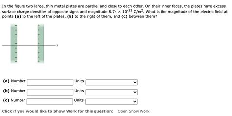
Table of Contents
Delving Deep into the Physics of Two Large, Thin Metal Plates: Capacitance, Electric Fields, and Beyond
In the realm of electromagnetism, the seemingly simple configuration of two large, thin, parallel metal plates offers a surprisingly rich landscape for exploration. This seemingly basic setup forms the foundation for understanding capacitors, a crucial component in countless electronic devices. This article will delve into the physics behind this arrangement, examining the electric field distribution, capacitance calculations, energy storage, and the effects of varying parameters such as plate separation and area. We'll also explore more advanced concepts and real-world applications.
Understanding the Electric Field Between Parallel Plates
The cornerstone of understanding the system of two large, thin metal plates lies in comprehending the electric field generated between them. When a potential difference (voltage) is applied across the plates, one plate becomes positively charged and the other negatively charged. This charge separation creates an electric field. Assuming the plates are much larger than their separation distance, we can employ the concept of infinite parallel plates as a useful approximation.
The Uniform Electric Field Approximation
For infinitely large plates, the electric field lines are nearly uniform and perpendicular to the plates within the region between them. This simplifies the analysis significantly. The electric field strength (E) is directly proportional to the surface charge density (σ) on the plates and inversely proportional to the permittivity of the medium (ε) between them:
E = σ/ε = V/d
Where:
- E represents the electric field strength (V/m)
- σ is the surface charge density (C/m²)
- ε is the permittivity of the medium (F/m) (ε₀ for vacuum or air)
- V is the potential difference (voltage) across the plates (V)
- d is the distance between the plates (m)
This equation highlights a crucial relationship: a larger voltage or smaller plate separation leads to a stronger electric field. The uniformity of the field is a key assumption, and it becomes increasingly accurate as the plate dimensions significantly exceed the separation distance.
Edge Effects and Non-Uniformity
The assumption of a uniform electric field breaks down near the edges of the plates. In reality, the electric field lines fringe out, creating a non-uniform field at the periphery. These fringe effects become increasingly significant as the plate dimensions approach the separation distance. Accurate calculations for real-world scenarios often require complex numerical methods or simulations to account for these edge effects. However, for plates significantly larger than their separation, the uniform field approximation provides a reasonably accurate model.
Capacitance: Storing Electrical Energy
The ability of the two plates to store electrical energy is quantified by their capacitance (C). Capacitance is a measure of how much charge can be stored on the plates for a given potential difference. For parallel plates, the capacitance is given by:
C = εA/d
Where:
- C is the capacitance (Farads, F)
- ε is the permittivity of the medium between the plates (F/m)
- A is the area of each plate (m²)
- d is the separation distance between the plates (m)
This equation reveals that capacitance increases with increasing plate area and decreasing plate separation. The choice of dielectric material between the plates also significantly influences capacitance. Materials with higher permittivity values store more charge for a given voltage.
The Role of the Dielectric
Introducing a dielectric material (an insulator) between the plates significantly increases the capacitance. The dielectric constant (κ) of the material modifies the permittivity, making the capacitance:
C = κεA/d
Dielectric materials reduce the electric field strength for a given charge, allowing for a greater charge accumulation at the same voltage. This enhancement is crucial in practical capacitor designs, enabling higher energy storage within a smaller volume. Common dielectric materials include ceramic, plastic films, and air.
Energy Stored in a Parallel Plate Capacitor
The energy (U) stored in a charged capacitor is given by:
U = (1/2)CV² = (1/2)QV = (1/2)Q²/C
Where:
- U is the stored energy (Joules, J)
- C is the capacitance (Farads, F)
- V is the voltage across the plates (V)
- Q is the charge stored on each plate (C)
This energy is stored in the electric field between the plates. Increasing the voltage, capacitance, or charge increases the stored energy. This energy storage capability makes capacitors essential components in numerous electronic circuits, acting as temporary energy reservoirs.
Applications of Parallel Plate Capacitors
The simple parallel plate capacitor, despite its apparent simplicity, finds widespread application in diverse fields:
Electronics:
- Filtering: Capacitors are used to filter out unwanted frequencies in electronic circuits, allowing only specific frequencies to pass through.
- Energy Storage: Capacitors provide temporary energy storage, crucial for smoothing out voltage fluctuations and powering devices during brief power interruptions.
- Timing Circuits: Capacitors combined with resistors form RC circuits used to control the timing of various operations in electronic devices.
- Coupling and Decoupling: Capacitors decouple circuits, preventing unwanted signals from interfering with each other.
- Tuning Circuits: In radio receivers, variable capacitors are used to tune into different radio frequencies.
Other Applications:
- Medical Devices: Capacitors are used in pacemakers and other implantable medical devices.
- Power Systems: Large capacitors are used in power systems for power factor correction and energy storage.
- Sensors: Capacitive sensors measure changes in capacitance, which can be used to detect changes in physical quantities like distance, pressure, or humidity.
- Photography: Flash units in cameras use large capacitors to store the energy required for a brief but powerful flash of light.
Beyond the Ideal: Real-World Considerations
While the analysis above provides a solid foundation, several factors deviate from the ideal model in real-world scenarios:
- Non-ideal Dielectrics: Real dielectric materials exhibit losses, meaning some energy is dissipated as heat during charging and discharging.
- Non-uniform Field: Edge effects cause non-uniform field distributions near the plate edges, influencing the overall performance.
- Plate Imperfections: Surface roughness and imperfections on the plates can affect capacitance and field uniformity.
- Temperature Dependence: Capacitance can vary with temperature, impacting circuit performance.
Advanced Concepts and Further Exploration
The study of parallel plate capacitors extends beyond the basics:
- Capacitor Networks: Understanding how capacitors behave when connected in series and parallel configurations is crucial for circuit design.
- Electrostatic Shielding: Parallel plates can be used for electrostatic shielding, protecting sensitive electronic components from external electric fields.
- Finite Element Analysis (FEA): Computational techniques like FEA can accurately model the electric field and capacitance for complex plate geometries.
- Applications in High-Energy Physics: High-voltage, high-capacitance systems are used in particle accelerators and other high-energy physics experiments.
Conclusion: A Foundation of Electromagnetism
The seemingly simple arrangement of two large, thin metal plates forms a cornerstone in understanding electromagnetism and its applications. While the ideal model provides a valuable starting point, understanding the limitations and delving into the more advanced concepts allows for a more complete grasp of the behavior of real-world capacitive systems. This knowledge is essential for engineers, physicists, and anyone interested in the fascinating world of electricity and electronics. The capacity to store and manipulate electrical energy, facilitated by these seemingly simple parallel plates, continues to shape our technological landscape.
Latest Posts
Latest Posts
-
This Pair Of Structures Anchors The Spindle
Mar 31, 2025
-
Oxidation State Of Cl In Clo3
Mar 31, 2025
-
A Solution Of H2so4 With A Molal Concentration Of
Mar 31, 2025
-
Chitin Is Composed Of Glucose And
Mar 31, 2025
-
Calculate Zeff For A Valence Electron In An Oxygen Atom
Mar 31, 2025
Related Post
Thank you for visiting our website which covers about In The Figure Two Large Thin Metal Plates . We hope the information provided has been useful to you. Feel free to contact us if you have any questions or need further assistance. See you next time and don't miss to bookmark.
