In The Figure The Current In Resistance 6 Is I6
News Leon
Mar 14, 2025 · 7 min read
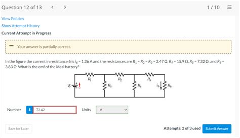
Table of Contents
Decoding Circuit Analysis: Understanding Current I6 in a Complex Circuit
Analyzing complex electrical circuits can be daunting, but a systematic approach using fundamental circuit laws and techniques can simplify the process. This article delves into the intricacies of determining the current (I6) flowing through a specific resistor (R6) within a larger circuit. We'll explore various methods, including Kirchhoff's Laws, nodal analysis, mesh analysis, and superposition, providing a comprehensive understanding of how to approach such problems. We'll also touch upon the importance of simplifying circuits and the practical implications of accurate current calculations.
Understanding the Context: Why I6 Matters
Before diving into the methodologies, it's crucial to understand the significance of determining I6. The current flowing through a resistor directly impacts several crucial aspects of the circuit:
-
Power Dissipation: The power dissipated by R6 (P6) is directly proportional to I6 squared (P6 = I6² * R6). Understanding I6 is vital for determining the power requirements and thermal management of the resistor, preventing overheating and potential component failure.
-
Voltage Drop: The voltage drop across R6 (V6) is directly proportional to I6 (V6 = I6 * R6). This voltage drop influences the voltage levels at other points in the circuit, affecting the operation of other components.
-
Circuit Behavior: The value of I6 can reveal valuable information about the overall behavior of the circuit. An unexpectedly high or low I6 could indicate a problem within the circuit, such as a short circuit or an open circuit.
-
Component Selection: Accurate calculation of I6 is crucial for selecting appropriately rated components. Resistors, for instance, must be able to handle the current without damage.
Method 1: Kirchhoff's Laws
Kirchhoff's Laws are foundational to circuit analysis. They consist of:
-
Kirchhoff's Current Law (KCL): The sum of currents entering a node (junction) is equal to the sum of currents leaving that node.
-
Kirchhoff's Voltage Law (KVL): The sum of voltage drops around any closed loop in a circuit is equal to zero.
To determine I6 using Kirchhoff's Laws, we need a specific circuit diagram. Let's assume a simple example:
(Imagine a circuit diagram here with multiple resistors and voltage sources, with R6 clearly labeled. A detailed description would be necessary instead of an actual diagram for this text-based format.)
Let's assume our circuit consists of three loops, with R6 being part of loop 3. We would apply KVL to each loop, generating a system of simultaneous equations involving the currents through each resistor. Solving this system would yield the values of all currents, including I6. This process often involves using matrix methods or other algebraic techniques for more complex circuits.
Example: Consider a simplified circuit with three resistors (R1, R2, R3) in series with a voltage source (V). We can easily determine the current (I) through the circuit using Ohm's Law (I = V/Rtotal), where Rtotal = R1 + R2 + R3. If R6 is part of this series, then I6 would be equal to I.
However, in a more complex circuit with parallel branches, we'd use KCL at the nodes to relate the currents in different branches before applying KVL to solve for I6.
Method 2: Nodal Analysis
Nodal analysis focuses on the node voltages in the circuit. We select a reference node (ground) and write KCL equations for each of the other nodes. These equations involve the node voltages and the conductances (reciprocal of resistance) of the connecting branches. Solving the resulting system of equations gives the node voltages, from which we can easily calculate the branch currents, including I6.
Advantages of Nodal Analysis:
- Efficient for circuits with many nodes: It often requires fewer equations than mesh analysis.
- Direct calculation of node voltages: Useful for analyzing circuits where node voltages are of primary interest.
Example: A circuit with multiple nodes and voltage sources would necessitate selecting a reference node and then writing a KCL equation for each of the remaining nodes. Solving this system of equations would provide the node voltages, leading to the calculation of I6 based on Ohm's Law (I6 = (Vnode1 - Vnode2) / R6).
Method 3: Mesh Analysis
Mesh analysis utilizes loop currents to analyze the circuit. We assign a loop current to each independent loop in the circuit. Then, we apply KVL to each loop, generating a system of equations involving the loop currents and the resistances. Solving these equations yields the loop currents, from which we can determine the branch currents, including I6.
Advantages of Mesh Analysis:
- Efficient for circuits with many loops: It can simplify calculations compared to nodal analysis in certain cases.
- Direct calculation of loop currents: Useful in circuits where loop currents are of primary interest.
Example: Assigning loop currents to each loop in a complex circuit and then applying KVL to each loop creates a system of equations. Solving these equations gives the loop currents. I6 would then be determined from the difference between two loop currents based on their respective paths through R6.
Method 4: Superposition
Superposition is a powerful technique that simplifies analysis by considering the effect of each independent source separately. We deactivate all but one source (voltage sources are shorted, current sources are opened), solve for I6 due to that single source, and then repeat the process for each source. Finally, we sum the individual contributions of I6 from each source to find the total I6.
Advantages of Superposition:
- Handles multiple sources effectively: This is particularly useful in circuits with several voltage and current sources.
- Simplification of analysis: Breaking down the complex circuit into simpler ones makes the calculations more manageable.
Example: If our circuit has multiple voltage sources, we’d short all but one source at a time, solving for I6 in each scenario. Adding up all the individual I6 values will give the total I6 in the original circuit.
Simplifying Complex Circuits: Techniques and Strategies
Before applying any of the above methods, simplifying the circuit is crucial. This can significantly reduce the complexity of the equations and makes the analysis more manageable. Some techniques include:
-
Series and Parallel Combinations: Combine resistors in series (Rtotal = R1 + R2 + ...) or parallel (1/Rtotal = 1/R1 + 1/R2 + ...) to reduce the number of components.
-
Source Transformations: Convert voltage sources with series resistors to current sources with parallel resistors, and vice-versa, to simplify the circuit topology.
-
Delta-Wye Transformations: Transform delta-connected resistors into wye-connected resistors (and vice-versa) to simplify the circuit configuration.
Careful application of these techniques can dramatically reduce the computational burden of determining I6.
Practical Implications and Error Handling
Accurate determination of I6 is not just a theoretical exercise; it has significant practical implications:
- Component Selection: Choosing components with appropriate current and power ratings is crucial to avoid failures.
- Circuit Design: I6 helps in optimizing circuit performance and ensuring it operates within specified parameters.
- Troubleshooting: Unexpected values of I6 can point towards faults within the circuit.
In practical circuit analysis, potential sources of error include:
- Measurement Errors: Inaccurate measurements of resistances and voltages can affect the calculated value of I6.
- Model Limitations: Simplified circuit models might not capture all the nuances of a real-world circuit.
- Computational Errors: Errors in algebraic manipulations or numerical solutions can lead to incorrect results.
Therefore, careful attention to detail, proper measurement techniques, and potentially using simulation software to verify results are essential for reliable outcomes.
Conclusion
Determining the current I6 in a complex circuit requires a systematic approach utilizing fundamental circuit laws and analytical techniques. While Kirchhoff's Laws, nodal analysis, mesh analysis, and superposition offer different pathways to the solution, the choice of method often depends on the specific circuit topology and the desired outcome. Remember that circuit simplification techniques are vital in reducing complexity, and meticulous attention to detail is crucial for achieving accurate and reliable results, preventing potential component damage or system malfunction. By mastering these methods, engineers and technicians can effectively analyze and design complex electrical circuits for diverse applications.
Latest Posts
Latest Posts
-
Which Of The Following Is Not A Renewable Energy Source
Mar 14, 2025
-
How Many Inches Are In One Cubic Foot
Mar 14, 2025
-
How Many Diodes Are Required To Form A Bridge Rectifier
Mar 14, 2025
-
A Graph Of The X Component Of The Electric Field
Mar 14, 2025
-
Reactions Which Do Not Continue To Completion Are Called Reactions
Mar 14, 2025
Related Post
Thank you for visiting our website which covers about In The Figure The Current In Resistance 6 Is I6 . We hope the information provided has been useful to you. Feel free to contact us if you have any questions or need further assistance. See you next time and don't miss to bookmark.
