How Is A Voltmeter Connected In A Circuit
News Leon
Apr 06, 2025 · 6 min read
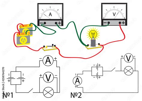
Table of Contents
How is a Voltmeter Connected in a Circuit? A Comprehensive Guide
Measuring voltage is fundamental in electronics and electrical engineering. Understanding how to correctly connect a voltmeter is crucial for accurate readings and, importantly, for your safety. This comprehensive guide explores the intricacies of voltmeter connection, covering various circuit configurations and potential pitfalls. We'll delve into the theory behind voltage measurement, practical applications, and troubleshooting common connection issues.
Understanding Voltage and Voltmeters
Before we dive into connection techniques, let's clarify the concept of voltage. Voltage, also known as potential difference, is the electrical pressure that pushes charged particles (electrons) through a circuit. It's measured in volts (V) and represents the energy difference between two points in a circuit. A higher voltage means a greater push, resulting in a stronger current flow.
A voltmeter is a measuring instrument used to measure the potential difference between two points in an electrical circuit. It's designed to have a very high internal resistance to minimize the current drawn from the circuit, ensuring the measurement doesn't significantly affect the circuit's operation. This high resistance is essential because drawing significant current could alter the voltage you're trying to measure, leading to inaccurate readings.
The Crucial Rule: Parallel Connection
The most important rule to remember when connecting a voltmeter is to always connect it in parallel across the component or section of the circuit where you want to measure the voltage. This means the voltmeter's leads are connected to the two points whose potential difference you wish to measure, without interrupting the circuit's normal current flow.
Think of it like this: Imagine a river (the circuit). The voltage is the difference in height between two points on the river. A voltmeter acts like a small dam that measures the height difference without significantly affecting the river's flow. Connecting it in series (like building a dam across the entire river) would disrupt the flow and provide an inaccurate, if any, reading.
Why Parallel Connection is Essential?
Connecting a voltmeter in series would be disastrous for several reasons:
- High Internal Resistance: The voltmeter's extremely high internal resistance would drastically reduce the current flowing through the circuit, potentially damaging or preventing the circuit from functioning correctly.
- Incorrect Readings: The voltage drop across the voltmeter itself would be the primary reading, completely masking the actual voltage across the component being measured.
- Circuit Overload: In some cases, the high internal resistance of the voltmeter might overload the circuit.
Connecting a Voltmeter: Step-by-Step Guide
Let's break down the process of connecting a voltmeter in different scenarios:
1. Measuring Voltage Across a Single Component (e.g., Resistor)
- Power OFF the circuit: This is crucial for safety! Always disconnect the power source before connecting or disconnecting any measuring instruments.
- Identify the component: Determine the specific component across which you need to measure the voltage.
- Connect the voltmeter leads: Connect the positive (+) lead of the voltmeter to one terminal of the component and the negative (-) lead to the other terminal. Ensure the leads are securely connected.
- Power ON the circuit: Carefully switch the power back on.
- Read the voltage: Observe the voltmeter's display to obtain the voltage reading.
- Power OFF the circuit: Once you've recorded the reading, turn the power off again before disconnecting the voltmeter.
2. Measuring Voltage Across Multiple Components
When measuring voltage across multiple components, you are measuring the combined voltage drop. The process remains the same, but you connect the leads across the start and end points of the section of the circuit you're interested in.
3. Measuring Voltage in a Complex Circuit
Complex circuits can pose a greater challenge, but the fundamental principle remains the same. Carefully trace the path of the circuit, identifying the points between which you wish to measure the voltage and connect the voltmeter accordingly in parallel.
4. Using a Multimeter (Voltmeter Function)
Many multimeters combine various measurement functions, including voltage, current, and resistance. The process of connecting a multimeter to measure voltage is identical to connecting a dedicated voltmeter. Remember to select the "voltage" function and appropriate voltage range on the multimeter before connecting it to the circuit.
Safety Precautions
Working with electricity necessitates prioritizing safety. Here are some critical safety measures to observe:
- Always disconnect the power source before connecting or disconnecting a voltmeter. This prevents electric shock.
- Ensure your voltmeter is properly rated for the voltage you're measuring. Using an inadequately rated voltmeter can damage the instrument and pose a safety risk.
- Never touch the exposed terminals or wires while the circuit is powered.
- Work in a well-lit, dry environment. Damp conditions increase the risk of electric shock.
- Use insulated tools and avoid wearing loose clothing or jewelry. These can accidentally come into contact with live wires.
- If you're unsure about anything, consult a qualified electrician.
Troubleshooting Common Connection Problems
Even with careful attention to detail, issues can arise. Here are some common problems and their solutions:
-
No reading:
- Check the power source: Ensure the circuit is powered on and the power source is functioning correctly.
- Verify the voltmeter's connections: Ensure the voltmeter leads are securely connected to the correct points in the circuit.
- Check the voltmeter's settings: Make sure the voltmeter is set to the correct voltage range.
- Check the fuses (if applicable): If the voltmeter has fuses, check whether they have blown.
-
Inaccurate readings:
- Check the voltmeter's calibration: Ensure the voltmeter is properly calibrated.
- Verify the leads' integrity: Ensure the test leads are not damaged or frayed.
- Check for stray capacitance or inductance: In high-frequency circuits, stray capacitance or inductance can affect readings.
- Consider load effects: The voltmeter itself draws a small current, which might slightly affect the circuit in some instances, particularly in circuits with very high internal resistance.
-
Damaged voltmeter: If you've checked all the above and still encounter issues, the voltmeter itself may be faulty and require repair or replacement.
Advanced Voltmeter Techniques
1. Measuring AC vs. DC Voltage
Voltmeters are capable of measuring both direct current (DC) and alternating current (AC) voltages. Remember to select the appropriate mode (AC or DC) on your voltmeter before making any measurement. AC voltage is sinusoidal and changes polarity periodically, while DC voltage is unidirectional.
2. Using High-Impedance Voltmeters
For particularly sensitive circuits, using a high-impedance voltmeter is crucial to minimize loading effects. High-impedance voltmeters draw minimal current, ensuring the circuit's operation isn't significantly disturbed during the measurement.
3. Differential Voltage Measurement
Some advanced voltmeters allow for differential voltage measurement, where the difference in potential between two arbitrary points in a circuit is measured. This technique is useful for measuring voltage drops across specific sections of a complex circuit.
4. Voltage Monitoring and Logging
Modern digital multimeters often include data logging capabilities. This enables continuous voltage monitoring and recording the readings over time, which is invaluable in various applications, including circuit debugging and system monitoring.
Conclusion
Correctly connecting a voltmeter is fundamental to accurate and safe electrical measurements. By following the principles outlined in this guide – always connecting in parallel, observing safety precautions, and troubleshooting potential problems – you can confidently measure voltage in a wide range of circuits. Remember to prioritize safety and always disconnect the power source before making any connections or disconnections. With practice and a thorough understanding of the concepts discussed, you'll master the art of voltage measurement and significantly improve your skills in electronics and electrical engineering.
Latest Posts
Latest Posts
-
How Many Chromosomes Do Onions Have
Apr 07, 2025
-
Points That Do Not Lie On The Same Line
Apr 07, 2025
-
Which Of The Following Are Input Devices
Apr 07, 2025
-
Are The Diagonals Of A Square Perpendicular
Apr 07, 2025
Related Post
Thank you for visiting our website which covers about How Is A Voltmeter Connected In A Circuit . We hope the information provided has been useful to you. Feel free to contact us if you have any questions or need further assistance. See you next time and don't miss to bookmark.
