Four Capacitors Are Connected As Shown In The Figure
News Leon
Mar 20, 2025 · 5 min read
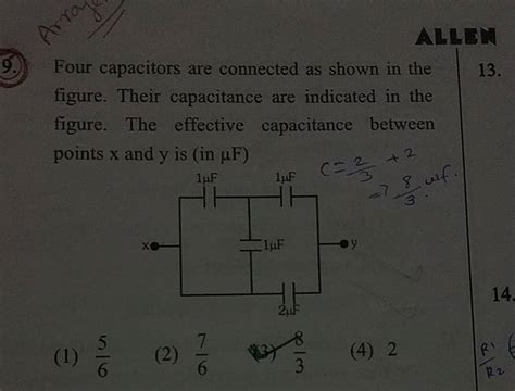
Table of Contents
Four Capacitors Connected: A Deep Dive into Series and Parallel Configurations
Understanding capacitor connections is fundamental to electronics. This article delves deep into the analysis of a circuit featuring four capacitors, exploring various connection methods, calculating equivalent capacitance, and discussing practical applications. We'll cover both series and parallel connections, exploring the implications of each configuration for total capacitance and voltage distribution. We'll also touch on the importance of capacitor selection and the impact of capacitance values on circuit performance.
Understanding Capacitors and Their Basic Connections
Before diving into the four-capacitor configuration, let's quickly review the basics. A capacitor is a passive two-terminal electrical component that stores electrical energy in an electric field. Its fundamental property is capacitance (measured in Farads, F), which represents the ability to store charge. The capacitance of a capacitor is determined by its physical characteristics – the area of the plates, the distance between them, and the dielectric material used.
Series Connection of Capacitors
When capacitors are connected in series, the total capacitance is less than the capacitance of the smallest individual capacitor. This is because the effective plate area decreases, and the distance between the plates effectively increases. The reciprocal of the equivalent capacitance (Ceq) is the sum of the reciprocals of the individual capacitances:
1/Ceq = 1/C1 + 1/C2 + 1/C3 + 1/C4
In a series connection, the voltage across each capacitor is inversely proportional to its capacitance. This means that a smaller capacitor will experience a larger voltage drop than a larger capacitor. This voltage distribution is crucial for circuit design and understanding potential voltage stresses on individual components.
Parallel Connection of Capacitors
In a parallel connection, the total capacitance is simply the sum of the individual capacitances:
Ceq = C1 + C2 + C3 + C4
This is because the effective plate area increases, providing more space for charge storage. The voltage across each capacitor in a parallel connection is the same. This simplifies analysis compared to the series configuration.
Analyzing Four Capacitors: Different Connection Possibilities
Now, let's examine various ways to connect four capacitors. The complexity increases significantly depending on how the capacitors are arranged. While a simple series or parallel arrangement is straightforward, more complex combinations introduce greater challenges in calculating equivalent capacitance and voltage distribution.
Scenario 1: All Four Capacitors in Series
Imagine all four capacitors (C1, C2, C3, and C4) are connected end-to-end in a single series chain. The equivalent capacitance is calculated using the formula mentioned earlier:
1/Ceq = 1/C1 + 1/C2 + 1/C3 + 1/C4
The voltage across each capacitor will vary inversely with its capacitance. For instance, if C1 is smaller than C2, C3, and C4, it will bear the highest voltage drop. This needs to be considered during circuit design to avoid exceeding the voltage rating of any individual capacitor.
Scenario 2: All Four Capacitors in Parallel
If all four capacitors are connected in parallel, the equivalent capacitance is simply the sum:
Ceq = C1 + C2 + C3 + C4
The voltage across each capacitor is the same, which simplifies circuit analysis considerably. This configuration maximizes the total energy storage capacity of the system.
Scenario 3: Two Pairs of Series Capacitors in Parallel
Consider a configuration where two pairs of capacitors are connected in series, and then those pairs are connected in parallel. For example, (C1 in series with C2) in parallel with (C3 in series with C4).
First, calculate the equivalent capacitance of each series pair:
- 1/Ceq12 = 1/C1 + 1/C2
- 1/Ceq34 = 1/C3 + 1/C4
Then, add these equivalent capacitances to find the total equivalent capacitance:
Ceq = Ceq12 + Ceq34
This configuration offers a balance between the smaller equivalent capacitance of a series connection and the ease of analysis offered by a parallel arrangement.
Scenario 4: More Complex Arrangements
Many other configurations are possible. For example, you could have a combination of series and parallel connections involving three capacitors in one branch and one capacitor in another, all connected in various series-parallel combinations. These scenarios demand a systematic approach. Using circuit simplification techniques and applying the series and parallel capacitance formulas stepwise will yield the total equivalent capacitance and help determine voltage distribution across each capacitor.
Practical Applications and Implications
Understanding how to calculate the equivalent capacitance of four capacitors in various configurations is crucial in several applications:
- Filtering: Capacitors are often used in filter circuits to block unwanted frequencies while allowing others to pass. The combination of capacitors can fine-tune the filtering characteristics.
- Energy Storage: In power supplies and energy storage systems, capacitors are used to store energy. By appropriately connecting multiple capacitors, you can achieve the desired energy storage capacity and voltage ratings.
- Timing Circuits: Capacitors play a critical role in timing circuits, influencing the timing of events within a system. Carefully selected capacitance values are essential for achieving precise timing.
- Resonant Circuits: In radio frequency circuits and oscillators, resonant circuits utilize the interplay between inductors and capacitors to achieve specific resonant frequencies. The selection of capacitors greatly impacts the resonant frequency of the circuit.
Capacitor Selection and Considerations
The selection of capacitors isn't merely about achieving the desired equivalent capacitance. Several other factors must be considered:
- Voltage Rating: Each capacitor has a maximum voltage rating that it can withstand without failure. Exceeding this rating can lead to capacitor breakdown and even circuit damage.
- Tolerance: Capacitors are manufactured with a certain tolerance, meaning the actual capacitance may vary slightly from the nominal value. This tolerance needs to be considered, especially in applications where precise capacitance is crucial.
- Temperature Dependence: The capacitance of a capacitor can change with temperature. This temperature dependence needs to be considered in applications that involve significant temperature variations.
- ESR (Equivalent Series Resistance): Every capacitor has an inherent resistance called ESR. This resistance can impact circuit performance, especially at high frequencies.
Conclusion: Mastering Capacitor Connections
Analyzing circuits with multiple capacitors, especially four, requires a clear understanding of series and parallel connections and their implications on the equivalent capacitance and voltage distribution. This article has provided a comprehensive overview of various connection possibilities, emphasizing the importance of systematic analysis and careful capacitor selection to achieve the desired circuit performance. By mastering these concepts, engineers and electronics enthusiasts can successfully design and analyze circuits involving multiple capacitors, unlocking a wide range of applications. Remember to always prioritize safety and select components with appropriate voltage and tolerance ratings for reliable circuit operation. Further study into specific capacitor types and their characteristics will deepen your understanding and proficiency in electronics design.
Latest Posts
Latest Posts
-
What Is 60 Percent Of 240
Mar 20, 2025
-
In 1991 The Soviet Union Collapsed Mainly Because
Mar 20, 2025
-
How Much Does A Drop Of Water Weigh
Mar 20, 2025
-
34 5 As A Mixed Number
Mar 20, 2025
-
The Size Of A Cell Is Limited By The
Mar 20, 2025
Related Post
Thank you for visiting our website which covers about Four Capacitors Are Connected As Shown In The Figure . We hope the information provided has been useful to you. Feel free to contact us if you have any questions or need further assistance. See you next time and don't miss to bookmark.
