Find The Current Through The 12 Ω Resistor.
News Leon
Mar 14, 2025 · 7 min read
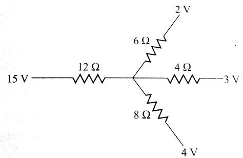
Table of Contents
Find the Current Through the 12Ω Resistor: A Comprehensive Guide
Determining the current flowing through a specific resistor within a complex circuit can seem daunting, but with a systematic approach and a solid understanding of fundamental circuit analysis techniques, it becomes a manageable task. This comprehensive guide will walk you through various methods to find the current through a 12Ω resistor, encompassing different circuit configurations and employing both simple and advanced techniques.
Understanding Basic Circuit Concepts
Before delving into specific problem-solving, let's solidify our understanding of core concepts:
Ohm's Law: The Foundation of Circuit Analysis
Ohm's Law is the bedrock of electrical circuit analysis. It states that the current (I) flowing through a conductor is directly proportional to the voltage (V) across it and inversely proportional to its resistance (R). Mathematically, this is represented as:
I = V/R
Where:
- I is the current measured in Amperes (A)
- V is the voltage measured in Volts (V)
- R is the resistance measured in Ohms (Ω)
Kirchhoff's Laws: Navigating Complex Circuits
For circuits more complex than a simple series or parallel arrangement, Kirchhoff's Laws become indispensable. These laws provide a systematic way to analyze circuits with multiple loops and branches:
-
Kirchhoff's Current Law (KCL): The sum of currents entering a node (junction) equals the sum of currents leaving that node. In simpler terms, current doesn't accumulate at a node; it flows through.
-
Kirchhoff's Voltage Law (KVL): The sum of voltage drops around any closed loop in a circuit equals zero. This reflects the principle of energy conservation – the voltage gained in a loop must equal the voltage lost.
Methods for Finding Current Through the 12Ω Resistor
The best method for determining the current through the 12Ω resistor depends heavily on the circuit's configuration. Let's explore several common scenarios and the appropriate techniques:
1. Simple Series Circuit
In a simple series circuit, all components (resistors, capacitors, etc.) are connected end-to-end, forming a single path for current flow. Calculating the current is straightforward:
-
Step 1: Calculate Total Resistance (R<sub>T</sub>): In a series circuit, the total resistance is simply the sum of individual resistances. If our circuit consists solely of the 12Ω resistor and other resistors,
R<sub>T</sub> = R<sub>1</sub> + R<sub>2</sub> + ... + R<sub>n</sub> + 12Ω. -
Step 2: Apply Ohm's Law: Use the total resistance and the source voltage (V<sub>S</sub>) to calculate the total current (I<sub>T</sub>) using Ohm's Law:
I<sub>T</sub> = V<sub>S</sub> / R<sub>T</sub>. -
Step 3: Determine Current Through 12Ω Resistor: In a series circuit, the current is the same throughout the entire circuit. Therefore, the current through the 12Ω resistor is equal to the total current:
I<sub>12Ω</sub> = I<sub>T</sub>.
Example: A simple series circuit with a 12V source, a 4Ω resistor, and a 12Ω resistor.
R<sub>T</sub> = 4Ω + 12Ω = 16Ω
I<sub>T</sub> = 12V / 16Ω = 0.75A
I<sub>12Ω</sub> = 0.75A
2. Simple Parallel Circuit
In a parallel circuit, components are connected across each other, providing multiple paths for current flow. The approach differs from the series circuit:
-
Step 1: Calculate Equivalent Resistance (R<sub>eq</sub>): For resistors in parallel, the reciprocal of the equivalent resistance is the sum of the reciprocals of individual resistances:
1/R<sub>eq</sub> = 1/R<sub>1</sub> + 1/R<sub>2</sub> + ... + 1/R<sub>n</sub>. If the 12Ω resistor is in parallel with other resistors, calculate R<sub>eq</sub> for that parallel branch. -
Step 2: Calculate Current Through the Parallel Branch: Use Ohm's Law to find the current (I<sub>branch</sub>) through the parallel branch:
I<sub>branch</sub> = V<sub>S</sub> / R<sub>eq</sub>. Remember that the voltage across each parallel branch is equal to the source voltage. -
Step 3: Determine Current Through 12Ω Resistor: Use Ohm's Law again, using the voltage across the 12Ω resistor (which is V<sub>S</sub> in a parallel branch) and its resistance:
I<sub>12Ω</sub> = V<sub>S</sub> / 12Ω.
Example: A 12V source with a 12Ω resistor in parallel with a 6Ω resistor.
1/R<sub>eq</sub> = 1/12Ω + 1/6Ω = 1/4Ω
R<sub>eq</sub> = 4Ω
I<sub>branch</sub> = 12V / 4Ω = 3A
I<sub>12Ω</sub> = 12V / 12Ω = 1A
3. Complex Circuits: Employing Kirchhoff's Laws and Other Techniques
For more complex circuits with multiple loops and branches, Kirchhoff's Laws combined with other techniques like nodal analysis or mesh analysis become essential.
-
Nodal Analysis: This technique focuses on the voltages at different nodes (junctions) in the circuit. You write KCL equations for each node, expressing currents in terms of voltages and resistances using Ohm's Law. This results in a system of linear equations that can be solved to find node voltages, from which you can then determine individual branch currents, including the current through the 12Ω resistor.
-
Mesh Analysis: This method focuses on the currents flowing in each loop (mesh) of the circuit. You write KVL equations for each loop, expressing voltage drops across resistors in terms of loop currents. Solving the resulting system of linear equations yields the loop currents, from which you can then determine the current through the 12Ω resistor.
-
Superposition Theorem: This powerful theorem simplifies analysis by considering the effect of each independent source in the circuit separately. You deactivate all but one source (short-circuiting voltage sources and open-circuiting current sources), calculate the current through the 12Ω resistor due to that single source, and then repeat for each source. The total current through the 12Ω resistor is the algebraic sum of the currents calculated for each individual source.
Example Scenario (Complex Circuit): Imagine a circuit with multiple voltage sources, several resistors including the 12Ω resistor, and both series and parallel connections. To find the current through the 12Ω resistor:
-
Draw a clear circuit diagram: A well-labeled diagram is crucial for accurate analysis.
-
Choose a suitable method: Nodal analysis or mesh analysis are generally the most efficient methods for complex circuits. The choice often depends on the number of nodes versus the number of meshes.
-
Write the equations: Based on your chosen method (nodal or mesh analysis), write a system of linear equations based on Kirchhoff's Laws and Ohm's Law.
-
Solve the equations: Use techniques like Gaussian elimination or matrix methods to solve the system of equations and determine the currents (including the current through the 12Ω resistor).
Solving complex circuits often involves simultaneous equations which can be solved using software tools like MATLAB, Python (with libraries like NumPy and SciPy), or dedicated circuit simulation software such as LTSpice or Multisim. These tools are extremely helpful for verifying your manual calculations and dealing with highly complex circuits.
Practical Considerations and Troubleshooting
-
Units: Always maintain consistent units throughout your calculations. Using volts for voltage, ohms for resistance, and amperes for current will prevent errors.
-
Circuit Simplification: Before applying complex techniques, try to simplify the circuit as much as possible by combining series or parallel resistors.
-
Verification: After calculating the current, verify your result using alternative methods or circuit simulation software. This helps identify potential errors.
-
Negative Current: A negative value for current indicates that the assumed direction of current flow is opposite to the actual direction.
Conclusion
Finding the current through a 12Ω resistor, or any resistor in a circuit, involves a systematic approach grounded in Ohm's Law and Kirchhoff's Laws. The choice of method depends entirely on the complexity of the circuit. For simple series and parallel circuits, direct application of Ohm's Law is sufficient. For more complex arrangements, nodal analysis, mesh analysis, or the superposition theorem provide powerful tools for accurate analysis. Remember to always double-check your work and utilize circuit simulation software when appropriate to ensure accuracy and gain deeper insight into circuit behavior. Mastering these techniques provides a strong foundation for tackling a wide range of electrical circuit problems.
Latest Posts
Latest Posts
-
Transactions Are Recorded In A Journal In
Mar 14, 2025
-
Which Of The Following Needs A Proof
Mar 14, 2025
-
Pure Substances Are Made Of Only One Type Of
Mar 14, 2025
-
A Dpt Vaccination Is An Example Of
Mar 14, 2025
-
Whats The Difference Between An Enzyme And A Hormone
Mar 14, 2025
Related Post
Thank you for visiting our website which covers about Find The Current Through The 12 Ω Resistor. . We hope the information provided has been useful to you. Feel free to contact us if you have any questions or need further assistance. See you next time and don't miss to bookmark.
