Each Plate Of A Parallel Plate Capacitor
News Leon
Mar 26, 2025 · 6 min read
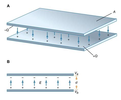
Table of Contents
Delving Deep into Each Plate of a Parallel Plate Capacitor
The parallel plate capacitor, a fundamental component in electronics and electromagnetism, is deceptively simple in its construction yet profoundly complex in its behavior. Understanding its function hinges on a thorough grasp of the properties and roles of its constituent parts: the two parallel plates. This article dives deep into the intricacies of each plate, exploring their individual characteristics and their collective contribution to the capacitor's overall performance. We will examine their material properties, charge distribution, electric field interactions, and the impact of various factors on capacitance.
The Individual Plate: A Conductor's Tale
Each plate of a parallel plate capacitor is typically made of a conductive material. Common choices include metals like copper, aluminum, or even specialized conductive polymers. The selection of material is influenced by factors such as cost, conductivity, dielectric strength of any intervening insulator, and the application's requirements. For instance, high-frequency applications might favor materials with low resistance and skin effect, while cost-sensitive applications might prioritize less expensive materials.
Key Characteristics of Each Plate:
-
Conductivity: The most critical property is the material's conductivity (σ). High conductivity ensures minimal energy loss as charge flows onto and off the plates. A high conductivity minimizes resistance, thus allowing for efficient charge storage and release. Lower conductivity leads to increased resistive losses and reduced capacitor efficiency.
-
Surface Area (A): The surface area of each plate directly impacts the capacitance. A larger surface area provides more space for charge accumulation, leading to a higher capacitance value. This relationship is directly proportional: doubling the area doubles the capacitance (holding other factors constant). This is a key design parameter for adjusting capacitor values.
-
Thickness (t): While the thickness of the plate itself doesn't directly affect the capacitance in an ideal scenario (assuming negligible resistance), it does influence other parameters. A thicker plate might have higher resistance, leading to energy losses. The choice of thickness often involves trade-offs between mechanical strength, weight, and electrical performance.
-
Material Uniformity: Consistency in the material's properties across the plate's surface is critical. Non-uniformities can lead to uneven charge distribution, potentially creating hot spots or localized failures. High quality control during manufacturing is essential to ensure uniform plate properties.
Charge Distribution and Electric Field
When a voltage is applied across the parallel plate capacitor, electrons flow from the negative terminal of the voltage source onto one plate, making it negatively charged. Simultaneously, electrons flow from the other plate to the positive terminal, leaving it positively charged. This charge accumulation is crucial to the capacitor's energy storage capability.
Understanding Charge Density:
The charge density (σ) is defined as the charge (Q) per unit area (A) on each plate: σ = Q/A. In an ideal parallel plate capacitor, the charge density is uniform across each plate's surface. However, in real-world scenarios, edge effects and imperfections can lead to slight non-uniformities in charge distribution. These deviations, while usually minor, can influence the precision of capacitance calculations.
Electric Field Formation:
The accumulation of opposite charges on the two plates creates an electric field (E) between them. This field is crucial for storing energy. In an ideal parallel plate capacitor with a uniform charge distribution, the electric field is uniform and perpendicular to the plates. The strength of the electric field is directly proportional to the charge density and inversely proportional to the permittivity of the dielectric material between the plates.
Electric Field Equation:
The electric field (E) between the plates can be expressed as:
E = σ / ε₀ (For a capacitor in a vacuum)
E = σ / ε (For a capacitor with a dielectric material)
Where:
- ε₀ is the permittivity of free space (approximately 8.854 x 10⁻¹² F/m)
- ε is the permittivity of the dielectric material
The Role of the Dielectric
The space between the two plates is not empty; it's typically filled with a dielectric material. The dielectric's permittivity (ε) plays a significant role in determining the capacitor's capacitance. A higher permittivity dielectric allows for greater charge storage at the same voltage. Common dielectric materials include air, ceramic, mica, plastic films (like polyethylene terephthalate or PET), and electrolytic solutions.
Dielectric Constant and Capacitance:
The dielectric constant (κ), which is the ratio of the dielectric's permittivity to the permittivity of free space (κ = ε/ε₀), directly affects capacitance. A higher dielectric constant means the capacitor can store more charge for the same voltage. This is reflected in the capacitance equation:
C = ε₀ * κ * A / d
Where:
- C is the capacitance
- A is the area of each plate
- d is the distance between the plates
Edge Effects and Non-Idealities
The above equations represent an idealized parallel plate capacitor. In reality, several factors deviate from this ideal model:
-
Fringing Fields: At the edges of the plates, the electric field lines are not perfectly uniform and "fringe" outwards. This effect increases the effective capacitance slightly.
-
Non-Uniform Charge Distribution: As previously mentioned, imperfections in the plates or the dielectric can lead to non-uniform charge distributions, impacting the field uniformity.
-
Plate Thickness: In a real-world capacitor, the finite thickness of the plates contributes to a slightly lower capacitance than predicted by the idealized equation.
-
Dielectric Losses: Real dielectric materials exhibit some energy losses due to factors like polarization and conductivity. These losses manifest as heat and reduce the capacitor's efficiency.
Capacitance Calculation Refinements
To account for edge effects and other non-idealities, more sophisticated methods are often used for capacitance calculations. These methods may involve numerical techniques like Finite Element Analysis (FEA) or more complex analytical models that incorporate fringing field effects. The choice of method depends on the accuracy required and the complexity of the capacitor's geometry.
Impact of Plate Separation (d)
The distance (d) between the plates is inversely proportional to the capacitance. Decreasing the distance increases the capacitance, allowing for more charge storage at the same voltage. However, reducing the distance too much can lead to electrical breakdown of the dielectric, potentially damaging the capacitor. The dielectric's breakdown voltage is a critical parameter that limits how close the plates can be placed.
Conclusion: Each Plate's Vital Role
Each plate in a parallel plate capacitor plays an equally crucial role in its function. Their material properties, surface area, and interaction with the dielectric determine the overall capacitance. Understanding the characteristics of each plate – from conductivity and surface area to the impact of edge effects and non-idealities – is essential for designing, selecting, and utilizing capacitors effectively in various electronic applications. While the idealized model provides a useful starting point, a thorough understanding of the nuances and limitations of real-world capacitors is necessary for optimal performance and reliability. The careful consideration of each plate’s contribution is therefore critical for successfully harnessing the energy storage capabilities of this ubiquitous electronic component.
Latest Posts
Latest Posts
-
How To Measure Meter Square Of A Room
Mar 29, 2025
-
Prevents Backflow Into The Left Atrium
Mar 29, 2025
-
What Is A Good Conductor Of Heat And Electrocty
Mar 29, 2025
-
A Group Of Cells With Similar Structure And Function
Mar 29, 2025
-
Integrate Sqrt A 2 X 2
Mar 29, 2025
Related Post
Thank you for visiting our website which covers about Each Plate Of A Parallel Plate Capacitor . We hope the information provided has been useful to you. Feel free to contact us if you have any questions or need further assistance. See you next time and don't miss to bookmark.
