Determine The Potential Difference Va-vb Shown In The Circuit Below
News Leon
Apr 07, 2025 · 7 min read
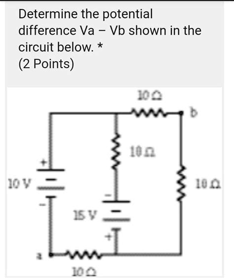
Table of Contents
Determining the Potential Difference V<sub>a</sub>-V<sub>b</sub>: A Comprehensive Guide
Determining potential difference, often represented as voltage, is a fundamental concept in electrical circuit analysis. This article delves into the process of calculating the potential difference V<sub>a</sub>-V<sub>b</sub> in a given circuit, covering various approaches and incorporating best practices for solving such problems. We will explore several methods, focusing on clarity and providing a step-by-step guide suitable for both beginners and experienced learners. Understanding this concept is crucial for mastering more complex circuit analysis techniques.
Understanding Potential Difference
Before diving into the calculations, let's clarify the concept of potential difference. Potential difference, or voltage, is the work done per unit charge in moving a charge between two points in an electric circuit. It's measured in volts (V). A potential difference exists when there's an imbalance of charge between two points, creating an electric field that drives the flow of current. In simpler terms, it's the electrical "pressure" that pushes electrons through a circuit. The potential difference V<sub>a</sub>-V<sub>b</sub> specifically refers to the voltage at point 'a' relative to point 'b'. A positive value indicates that point 'a' is at a higher potential than point 'b'.
Essential Circuit Analysis Tools & Techniques
To successfully determine V<sub>a</sub>-V<sub>b</sub>, we need to familiarize ourselves with several key tools and techniques used in circuit analysis:
1. Ohm's Law
Ohm's Law is the cornerstone of circuit analysis. It states that the current (I) flowing through a resistor is directly proportional to the voltage (V) across it and inversely proportional to its resistance (R). Mathematically, it's expressed as:
V = IR
This simple yet powerful equation allows us to calculate any of the three variables (V, I, R) if the other two are known.
2. Kirchhoff's Laws
Kirchhoff's Laws are fundamental principles governing the behavior of current and voltage in electrical circuits. They consist of two laws:
-
Kirchhoff's Current Law (KCL): The sum of currents entering a node (junction) equals the sum of currents leaving that node. This reflects the principle of charge conservation.
-
Kirchhoff's Voltage Law (KVL): The sum of the voltage drops around any closed loop in a circuit is zero. This reflects the principle of energy conservation.
These laws are crucial for analyzing complex circuits where Ohm's Law alone isn't sufficient.
3. Series and Parallel Resistor Combinations
Understanding how resistors combine in series and parallel circuits is vital.
-
Series Resistors: The total resistance (R<sub>total</sub>) of resistors connected in series is simply the sum of their individual resistances:
R<sub>total</sub> = R<sub>1</sub> + R<sub>2</sub> + R<sub>3</sub> + ...
-
Parallel Resistors: The reciprocal of the total resistance of resistors connected in parallel is equal to the sum of the reciprocals of their individual resistances:
1/R<sub>total</sub> = 1/R<sub>1</sub> + 1/R<sub>2</sub> + 1/R<sub>3</sub> + ...
These formulas allow us to simplify circuits before applying Ohm's Law or Kirchhoff's Laws.
4. Node Voltage Analysis
Node voltage analysis is a powerful technique used to solve complex circuits. It involves selecting a reference node (usually the ground) and then determining the voltage at each other node in the circuit relative to the reference node. This method often simplifies the solution process, especially for circuits with many branches.
Solving for V<sub>a</sub>-V<sub>b</sub>: A Step-by-Step Approach
To illustrate the process, let's consider a sample circuit (Note: Since I cannot display images, I will describe a sample circuit. You will need to visualize or draw the circuit yourself).
Sample Circuit Description:
Imagine a circuit with a 12V battery. From the positive terminal of the battery, a branch splits into two parallel resistors: R1 (4 ohms) and R2 (6 ohms). Point 'a' is located at the junction point before these parallel resistors. Point 'b' is located at the junction point where the two parallel resistors connect back together, before the negative terminal of the battery.
Steps to Determine V<sub>a</sub>-V<sub>b</sub>:
-
Simplify the Circuit: We have parallel resistors (R1 and R2). We calculate the equivalent resistance (R<sub>eq</sub>) of this parallel combination:
1/R<sub>eq</sub> = 1/4 + 1/6 = 5/12 R<sub>eq</sub> = 12/5 = 2.4 ohms
-
Apply Ohm's Law: The entire circuit now simplifies to a single loop with the battery and R<sub>eq</sub>. Using Ohm's Law, we can calculate the total current (I) flowing through the circuit:
I = V / R<sub>eq</sub> = 12V / 2.4 ohms = 5A
-
Calculate Voltage Drops across Parallel Resistors: The voltage across parallel resistors is always the same. Because point 'a' is before the parallel resistors and point 'b' is after the parallel resistors the total voltage drop from 'a' to 'b' will be equivalent to the voltage across the equivalent resistance R<sub>eq</sub>. Therefore, V<sub>a</sub> - V<sub>b</sub> is equal to the voltage drop across R<sub>eq</sub>, which is 12V.
-
Alternative Approach using KVL: Alternatively, we can use Kirchhoff's Voltage Law (KVL). Starting at point 'a', moving through the parallel resistors, and returning to 'a', the sum of voltage drops must be zero. Therefore:
V<sub>a</sub> - V<sub>R1</sub> - V<sub>b</sub> = 0 (where V<sub>R1</sub> is the voltage drop across R1).
Since the voltage across parallel branches is the same, V<sub>R1</sub>=V<sub>R2</sub>=V<sub>ab</sub>=12V.Therefore, V<sub>a</sub> - V<sub>b</sub> = V<sub>ab</sub> = 12V
Conclusion:
In this simple example, V<sub>a</sub>-V<sub>b</sub> is equal to the battery voltage (12V). This is because there are no other components between points 'a' and 'b' contributing to a voltage drop. In more complex circuits, applying Kirchhoff's Laws, Ohm's Law, and potentially node voltage analysis will be necessary for a step-by-step approach in determining the potential difference between any two points.
Advanced Scenarios and Considerations
The previous example demonstrates a relatively simple circuit. Let's explore more complex scenarios:
Circuits with Multiple Voltage Sources
Circuits with multiple voltage sources require a more systematic approach, typically using either nodal analysis or mesh analysis. Nodal analysis focuses on the nodes (junction points) in the circuit, while mesh analysis focuses on the loops. Both methods involve setting up and solving simultaneous equations based on Kirchhoff's Laws.
Circuits with Dependent Sources
Dependent sources, whose values depend on other voltages or currents in the circuit, add another layer of complexity. These sources often require iterative solutions or more advanced techniques like superposition.
AC Circuits
The principles discussed above apply equally well to DC circuits. However, AC circuits introduce the concept of impedance (complex resistance) and require the use of phasors and complex numbers for calculations. The same laws still apply but the calculations will be more complex to accommodate the sinusoidal nature of AC signals.
Non-linear Components
Components like diodes and transistors exhibit non-linear behavior, meaning their voltage-current relationship is not linear. Analyzing circuits with such components often requires numerical methods or specialized software simulations.
Practical Applications and Importance
Determining potential difference is crucial in various applications:
-
Electronics Design: Calculating voltage drops across components is essential for circuit design to ensure proper operation and prevent component damage.
-
Power Systems Analysis: Understanding voltage levels and drops is vital for efficient power distribution and minimizing losses.
-
Instrumentation and Measurement: Voltage measurements are essential for monitoring and controlling various parameters in industrial and scientific applications.
-
Troubleshooting and Fault Diagnosis: Voltage measurements are critical for identifying faults and troubleshooting problems in electrical circuits and systems.
Conclusion
Determining the potential difference V<sub>a</sub>-V<sub>b</sub>, or any potential difference for that matter, in a circuit involves understanding fundamental circuit analysis principles like Ohm's Law and Kirchhoff's Laws. The specific techniques applied depend on the circuit's complexity. Mastering these techniques is paramount for success in electrical engineering, electronics design, and related fields. By following a systematic, step-by-step approach and understanding the underlying principles, one can confidently analyze and solve for potential differences in even the most complex circuits. Remember to always check your work and use multiple methods to verify your calculations for accuracy and thoroughness.
Latest Posts
Latest Posts
-
Find The Geometric Mean Of 9 And 16
Apr 08, 2025
-
Can A Compound Be Separated By Physical Means
Apr 08, 2025
-
Find The Magnitude Of The Electric Dipole Moment
Apr 08, 2025
-
Log 1 Log 2 Log 3
Apr 08, 2025
-
What Part Of The Cell Transports Materials Within The Cell
Apr 08, 2025
Related Post
Thank you for visiting our website which covers about Determine The Potential Difference Va-vb Shown In The Circuit Below . We hope the information provided has been useful to you. Feel free to contact us if you have any questions or need further assistance. See you next time and don't miss to bookmark.